Vehicle Power Controller

a technology for power controllers and vehicles, applied in emergency power supply arrangements, motor/generator/converter stoppers, electric devices, etc., can solve problems such as delay in charging to secondary batteries, and achieve the effect of large regenerative energy and appropriately estimated regenerative energy

Inactive Publication Date: 2009-07-02
TOYOTA JIDOSHA KK
View PDF14 Cites 24 Cited by
  • Summary
  • Abstract
  • Description
  • Claims
  • Application Information

AI Technical Summary

Benefits of technology

[0026]According to the present invention, if the vehicle runs a long, steep downhill, for example, the driver often requires regenerative braking force that matches the inclination. Specifically, it is often the case that large regenerative energy generates as the large regenerative power continues for a long period of time. Therefore, whether a large regenerative energy would be generated or not is estimated based on

Problems solved by technology

Specifically, though the amount of charges to the capacitor is the same, charging to th

Method used


Image

  • Vehicle Power Controller
  • Vehicle Power Controller
  • Vehicle Power Controller

Examples


first embodiment

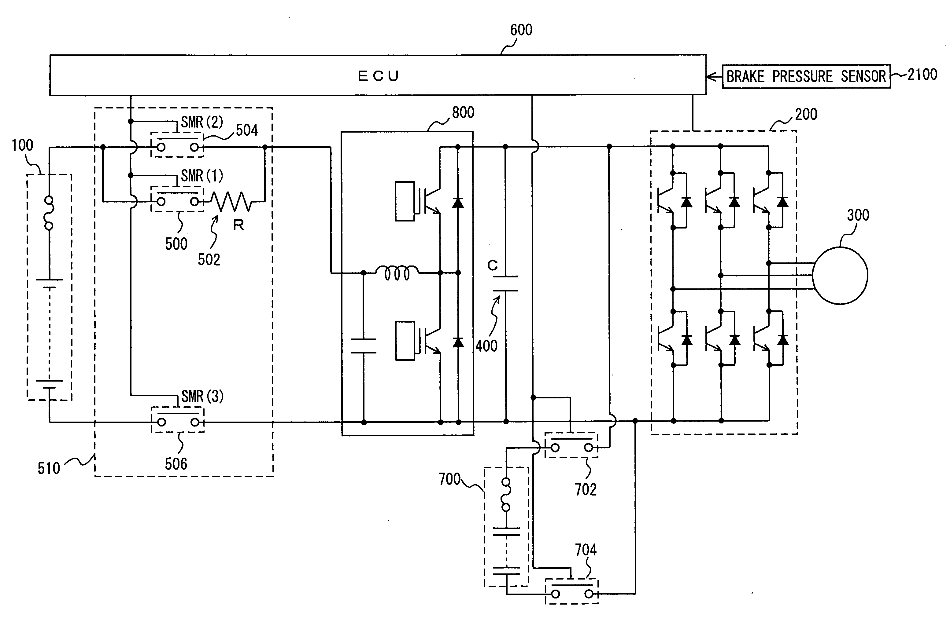
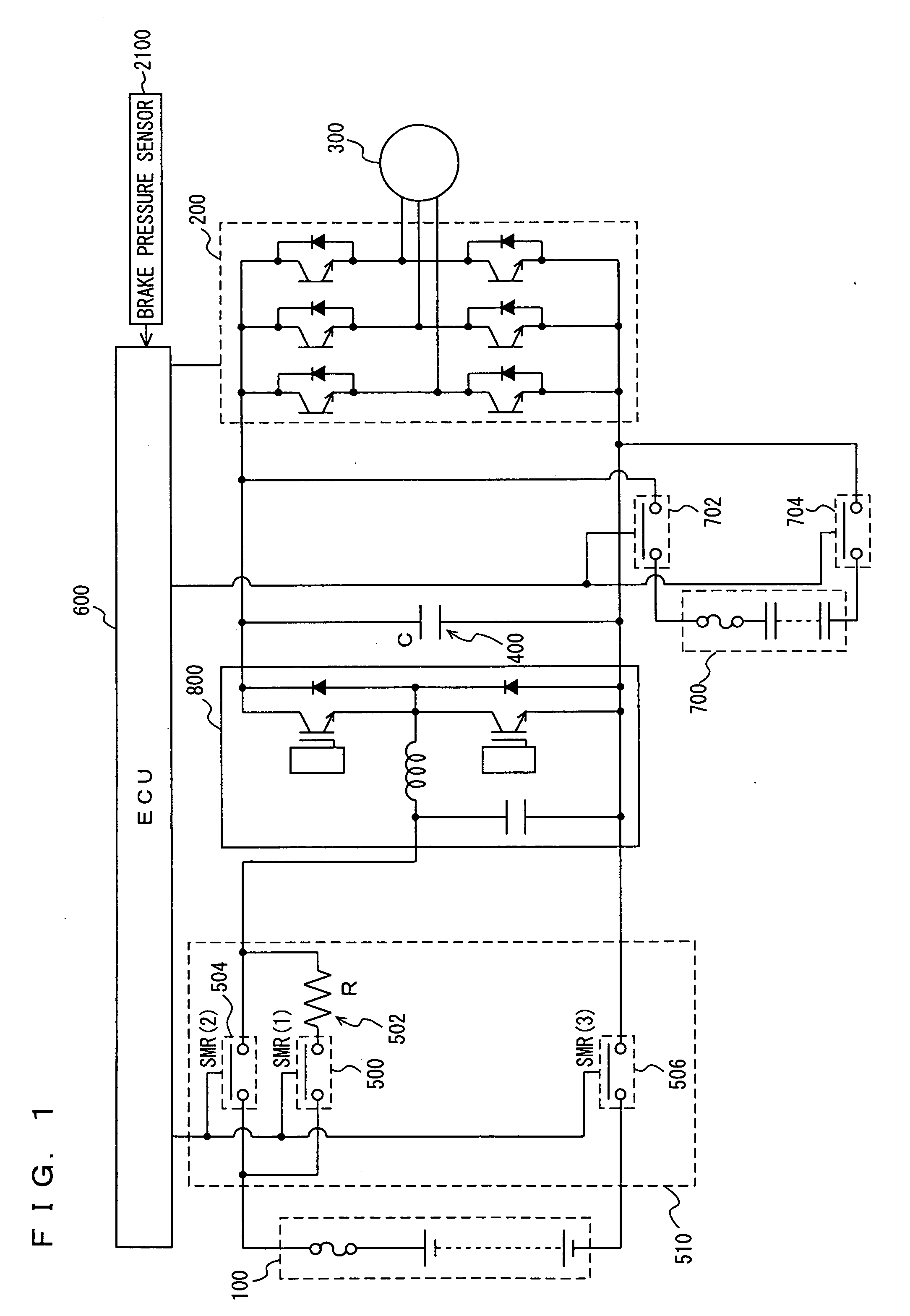
[0036]Referring to FIG. 1, the vehicle mounting the power controller in accordance with the embodiment of the present invention will be described. The vehicle includes: a battery 100; an inverter 200; a motor generator 300; a condenser 400; a system main relay 510 (SMR (1) 500, limiting resistor 502, SMR (2) 504, SMR (3) 506); and an ECU (Electronic Control Unit) 600. The power controller in accordance with the present embodiment is controlled by a program executed by ECU 600. In the present embodiment, the vehicle will be described as an electric vehicle that runs only by the driving force from motor generator 300. The vehicle on which power controller of the present invention is mountable is not limited to the electric vehicle, and it may be mounted on a hybrid vehicle, a fuel cell electric vehicle or the like.

[0037]Battery 100 is a battery assembly connecting in series a plurality of modules, each including a plurality of cells connected in series. In addition to battery 100, a c...

second embodiment

[0071]A power controller in accordance with the present embodiment will be described. The power controller of the present embodiment differs from the structure of power controller in accordance with the first embodiment described above in that it includes a navigation device 2200 and an ECU 1600, in place of brake pressure sensor 2100 and ECU 600. ECU 1600 differs from ECU 600 implementing the power controller in accordance with the first embodiment only in the control structure of the program. Except for these points, the structure is the same as the power controller in accordance with the first embodiment described above. The same components are denoted by the same reference characters. Their functions are also the same. Therefore, detailed description thereof will not be repeated here.

[0072]Referring to FIG. 7, the vehicle mounting the power controller in accordance with the present embodiment will be described.

[0073]Navigation device 2200 calculates vehicle running information b...


PUM


Abstract

An ECU executes a program including the steps of: calculating regenerative power value P based on a brake pressure (S100); calculating limit charging power WIN(B) to a battery (S102); calculating limit charging power WIN(C) to a capacitor (S104); when it is determined that regenerative power value P is larger than the sum of WIN(B) and WIN(C) (YES at S106), estimating (S108) that a large regenerative energy sufficient to fully charge the capacitor even if the battery is charged with priority would be generated; and transmitting a control signal (S110) to set output voltage of a boost converter to be not higher than the voltage of the capacitor so as to charge the battery with priority.

Description

TECHNICAL FIELD[0001]The present invention relates to a power controller for a vehicle including a rotating electric machine for running that generates regenerative electric power at the time of regenerative braking and, specifically, to a power controller for a vehicle provided with a battery and a capacitor that are charged with the regenerative power.BACKGROUND ART[0002]A vehicle mounting a power train referred to as a hybrid system, in which an engine (possibly a known mechanism such as a gasoline engine or a diesel engine) and a motor are combined, has been developed and commercially available. Further, a vehicle (electric vehicle, fuel cell electric vehicle) mounting a power train using only the motor as the running source and not mounting any engine, has also been developed. Such a vehicle mounts an electric storage mechanism (a battery or a capacitor) for motor drive. At the time of acceleration of the vehicle, the motor is driven by the electric power supplied from the elec...

Claims


Application Information

Patent Timeline
IPC IPC(8): H02P3/14
CPCB60L3/0046Y02T90/121B60L9/18B60L11/18B60L11/1803B60L11/185B60L11/1861B60L15/2009B60L2210/14Y02T10/7005Y02T10/7044Y02T10/705Y02T10/7225Y02T90/127Y02T90/128Y02T90/14Y02T10/7275B60L7/26Y02T10/7072B60L50/51B60L53/11B60L58/12B60L50/60B60L58/24Y02T10/70Y02T10/64Y02T10/72B60L7/14B60K6/28H02P3/14B60W10/24Y02T90/12
Inventor SOMA, TAKAYAYOSHIDA, HIROSHIMOGARI, TAKESHI
Owner TOYOTA JIDOSHA KK
Why Eureka
Try Eureka