
Regeneration Control Device for Vehicle

a technology of regenerative control and control device, which is applied in the direction of motor/generator/converter stopper, dynamo-electric converter control, battery/fuel cell control arrangement, etc. it can solve the problems of cell batteries constituting the battery system that cannot receive the power regenerated by the motor, power cannot be supplied to the motor, and the performance of cell batteries can be affected by degradation. , to achieve the effect of preventing degradation of cell batteries and recovering larger regenerated energy

Inactive Publication Date: 2015-09-17
HITACHI AUTOMOTIVE SYST LTD
View PDF9 Cites 36 Cited by
  • Summary
  • Abstract
  • Description
  • Claims
  • Application Information

AI Technical Summary

Benefits of technology

The present invention prevents cell batteries from reaching a point where they cannot perform their function properly (regeneration inhibiting voltage), even during initial braking when the vehicle is going at a high speed. This is done by setting a limit on the amount of regeneration power that can be used, based on the state of the batteries. By doing this, the invention ensures that the batteries are securely protected and more energy can be recovered during braking.

Problems solved by technology

For example, if the state of charge (SOC) of the cell battery is in the state of full charge, the battery system cannot receive the power regenerated by the motor.
In addition, if the charged capacity of the cell batteries is small, power cannot be supplied to the motor.
Cell batteries constituting the battery system may be affected by degradation of their performance, which may occur depending on their usage.
For example, if the voltage across terminals of a cell battery reaches a predetermined charge / regeneration inhibiting voltage or above to cause overvoltage or is decreased to a predetermined voltage or below, degradation of the performance of the cell battery may occur.

Method used


Image

  • Regeneration Control Device for Vehicle
  • Regeneration Control Device for Vehicle
  • Regeneration Control Device for Vehicle

Examples


Embodiment Construction

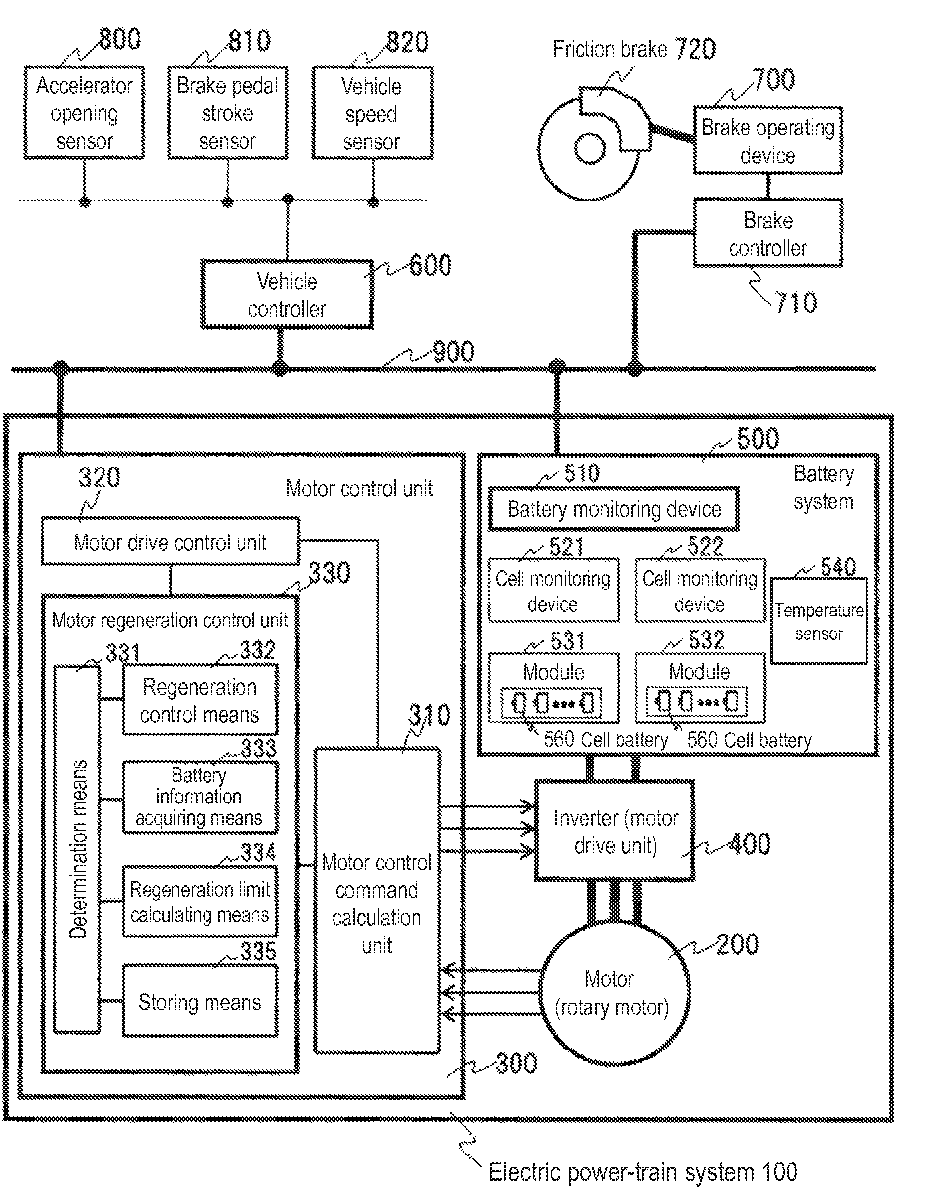
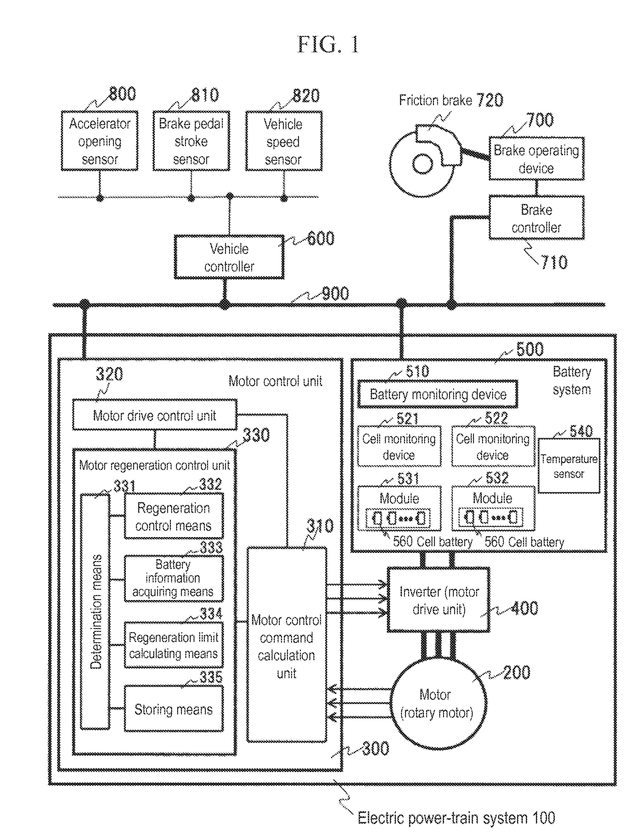
[0038]FIG. 1 illustrates an example of an electric power-train system 100 to which a regeneration control device of the present invention is applied as an outline of the entire system.

[0039]The electric power-train system 100 includes a motor 200 which is a rotary motor, an inverter 400 which is a motor drive unit, a motor control unit 300 which outputs a control command for the inverter, and a battery system 500 which supplies power to the inverter 400.

[0040]The motor control unit 300 of the electric power-train 100 is installed in a vehicle, and is connected via a vehicle controller 600, which controls the entire vehicle, a brake controller 710, which operates a command for a brake operating device 700 which operates a friction brake 720, and a control area network 900.

[0041]The vehicle controller 600 which controls the entire vehicle receives detection signals from sensors such as an accelerator opening sensor 800, a brake pedal stroke sensor 810, and a vehicle speed sensor 820 a...


PUM


Abstract

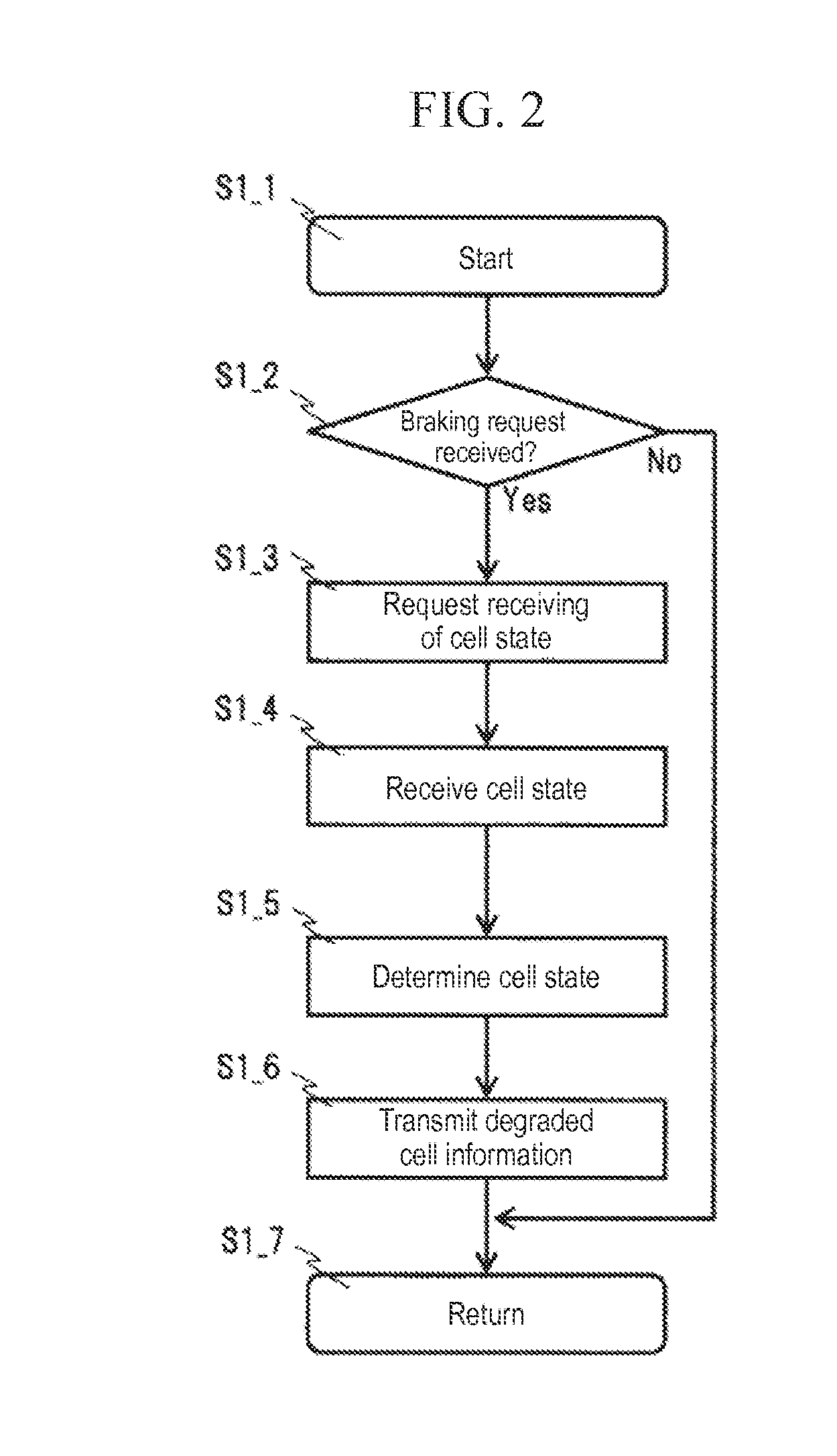
In order to prevent cell batteries from reaching a regeneration inhibiting voltage in an initial period of regeneration braking and to ensure that a large amount of regeneration can be secured even if characteristics of cell batteries are varied, when a vehicle braking request is received (S2-2), a first limit of regeneration power (S2-8) for which the amount of regeneration is relatively small is performed, and while regeneration control is being performed, information about the cell batteries such as voltage across terminals is acquired from a battery monitoring device to identify a cell battery of which the voltage across terminals becomes the highest among the multiple cell batteries. After the determination is completed (S2-5), the process proceeds to a second regeneration control (S2-9). In the second regeneration control, regeneration is performed by using an upper limit amount of regeneration with which an identified worst cell battery would not reach the regeneration inhibiting voltage as a limiting value.

Description

TECHNICAL FIELD[0001]The present invention relates to a regeneration control device for preventing degradation of a cell battery that may occur due to overvoltage during regeneration, which is used in a vehicle capable of performing braking using energy regenerated in a motor, such as an electric vehicle or a hybrid electric vehicle.BACKGROUND ART[0002]Conventionally, a technique has been known in which a motor that is a rotary electric motor is installed as a power source of an electric vehicle or a hybrid electric vehicle, for example, an inverter that is a motor drive unit is provided between the motor and an electric power supply unit, and a motor control unit which controls torque and the like of the motor is provided so that the inverter supplies a motor current that is a motor drive signal to drive the motor. The inverter converts direct current (DC) power from the electric power supply unit into alternate current (AC) power that is determined in accordance with a torque refe...

Claims


Application Information

Patent Timeline
IPC IPC(8): B60L7/18H02P3/14B60L3/00B60L7/14H02J7/00H02J7/02
CPCH02P3/14B60L7/18B60L7/14H01M10/482B60L3/0046B60L3/04B60L7/26B60L15/2009B60L2220/14B60L2240/12B60L2240/421B60L2240/423B60L2240/545B60L2240/547B60L2240/549B60L2240/80B60L2250/26Y02T10/72B60L2220/16B60L50/51B60L58/16B60L58/13B60L58/21B60L58/15B60L58/18Y02T10/64Y02T10/70Y02E60/10
Inventor OKADA, TAKASHIMIYAZAKI, HIDEKIOYAMA, KAZUTOKOJIMA, TAKAO
Owner HITACHI AUTOMOTIVE SYST LTD
Learn More