Current zero crossing detector in a dimmer circuit

Inactive Publication Date: 2009-07-02
CLIPSAL AUSTRALIA
View PDF14 Cites 16 Cited by
  • Summary
  • Abstract
  • Description
  • Claims
  • Application Information

AI Technical Summary

Benefits of technology

[0020]In one form, the value of the reference voltage is increased up to a maximum reference voltage exponentially.
[0021]According to a second aspect of the present invention, there is provided a circuit for controlling the delivery of power having a current component to a load having

Problems solved by technology

Turning off the switch while there is any appreciable level of current causes a sudden rise in the voltage appearing across the load.
However, since the current sense resistor adds to the total resistance of the dimmer, it results in more power being drained by the dimmer.
This

Method used


Image

  • Current zero crossing detector in a dimmer circuit
  • Current zero crossing detector in a dimmer circuit
  • Current zero crossing detector in a dimmer circuit

Examples


Example

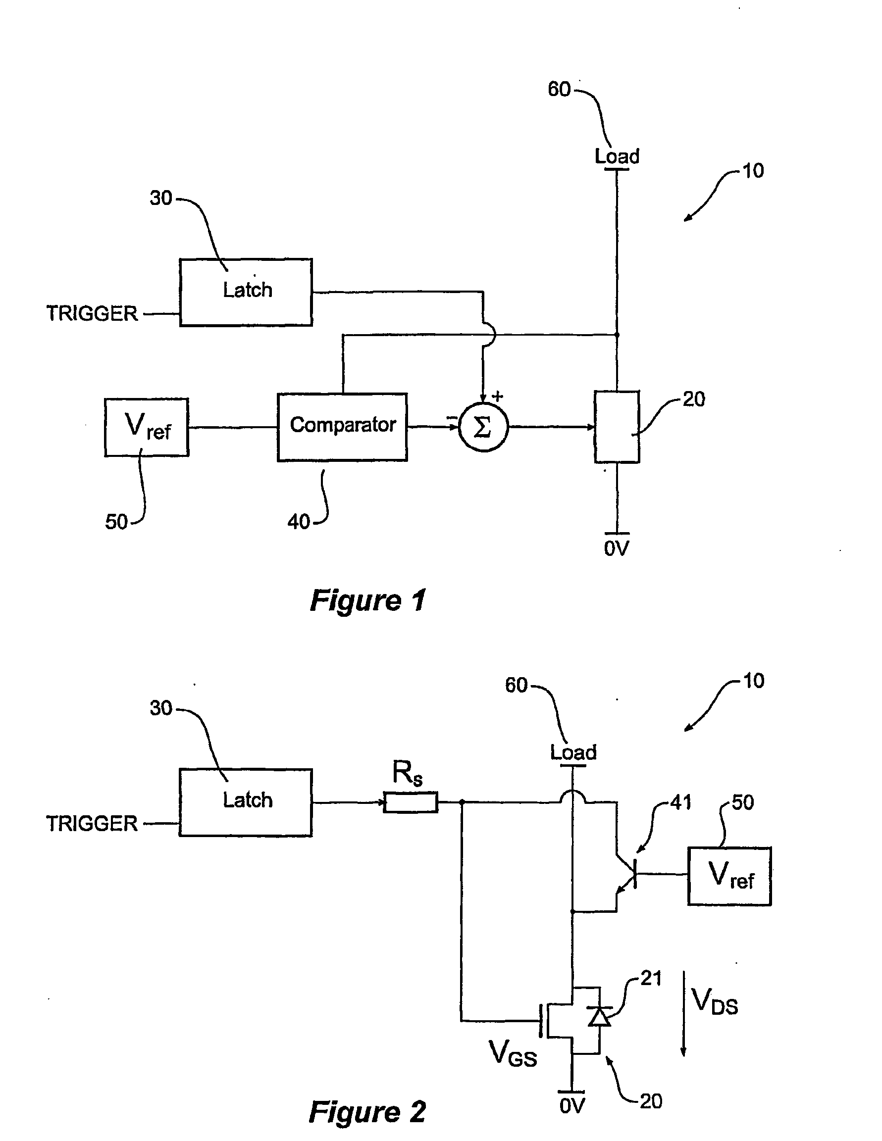
[0046]Throughout this specification, the terms “linear mode” and “saturation mode” are used to describe various aspects of the present invention. It will be understood that the term “linear mode”, when used in relation to a switch such as a MOSFET, means that the switch exhibits a resistive V / I characteristic, i.e. VDS=RDS×IL; where VDS is the Drain-Source voltage of the switch, RDS is the Drain-Source resistance and IL is the load current. It will also be understood that the term “saturation mode” refers to the state in which the VDS of the switch is not a function of current (determined by VGS magnitude, where VGS is the Gate-Source voltage).

[0047]FIG. 1 shows a block diagram of an arrangement 10 for controlling power delivered to load 60 by switch 20. A feedback signal Vf / b proportional to the voltage across the switch 20 is provided to one input of commutation control block 40 (provided by a comparator), which compares this feedback signal with a reference voltage Vref provided ...


PUM


Abstract

A method and circuit for controlling the delivery of power having a current component to a load having an inductive component, the method comprising selectively switching power to the load with a switch, wherein the switch is caused to operate at the threshold of saturation during a conduction state such that the switch self commutates to its off state when the magnitude of the current through the load is substantially zero. The method and circuit may be used in a number of applications for detecting a current zero crossing and may be applied to circuits such as dimmer circuits.

Description

TECHNICAL FIELD[0001]This invention relates to dimmer circuits and in particular, to controlling the switching of a dimmer circuit controlling inductive loads.PRIORITY[0002]This application claims priority from Australian Provisional Patent Application No. 2005906950 entitled “Current Zero Crossing Detector in a Dimmer Circuit”, and filed on 12 Dec. 2005.[0003]The entire content of this provisional application is hereby incorporated by reference.BACKGROUND[0004]Dimmer circuits are used to control the power provided to a load such as a light or electric motor from a power source such as mains. Such circuits often use a technique referred to as phase controlled dimming. This allows power provided to the load to be controlled by varying the amount of time that a switch connecting the load to the power source is conducting during a given cycle.[0005]For example, if voltage provided by the power source can be represented by a sine wave, then maximum power is provided to the load if the s...

Claims


Application Information

Patent Timeline
IPC IPC(8): G05F1/10
CPCH03K17/133H05B39/02H03K17/6877H03K17/6874
Inventor VANDERZON, JAMES ROBERT
Owner CLIPSAL AUSTRALIA
Why Eureka
Try Eureka