Method and Apparatus for Magnetic Resonance Analysis

Inactive Publication Date: 2009-07-02
RAMOT AT TEL AVIV UNIV LTD
View PDF11 Cites 3 Cited by
  • Summary
  • Abstract
  • Description
  • Claims
  • Application Information

AI Technical Summary

Benefits of technology

[0016]According to one aspect of the present invention there is provided a method of magnetic resonance analysis of a body having therein at least one molecular species and water. The method comprises: subtracting magnetic resonance signals induced by a second radiofrequency pulse sequence from magnetic resonance signals induced by a first radiofrequency pulse sequence followed by a e

Problems solved by technology

However, when these systems are imaged, the acquisition of the signal from the protein is practically impossible because for most clinical systems this signal decays off prior or very shortly after such acquisition starts.
A major disadvantage of the techniques disclosed in Neufeld et al. and Carasso et al. supra is that they require very short radiofrequency pulses having homogenous radiofrequency magnetic field.
However, presently available clinical MRI scanners, particularly whole body scanners in which large radiofrequency coils are deployed, require much longer radiofrequency pulses.

Method used


Image

  • Method and Apparatus for Magnetic Resonance Analysis
  • Method and Apparatus for Magnetic Resonance Analysis
  • Method and Apparatus for Magnetic Resonance Analysis

Examples


example 1

Materials and Methods

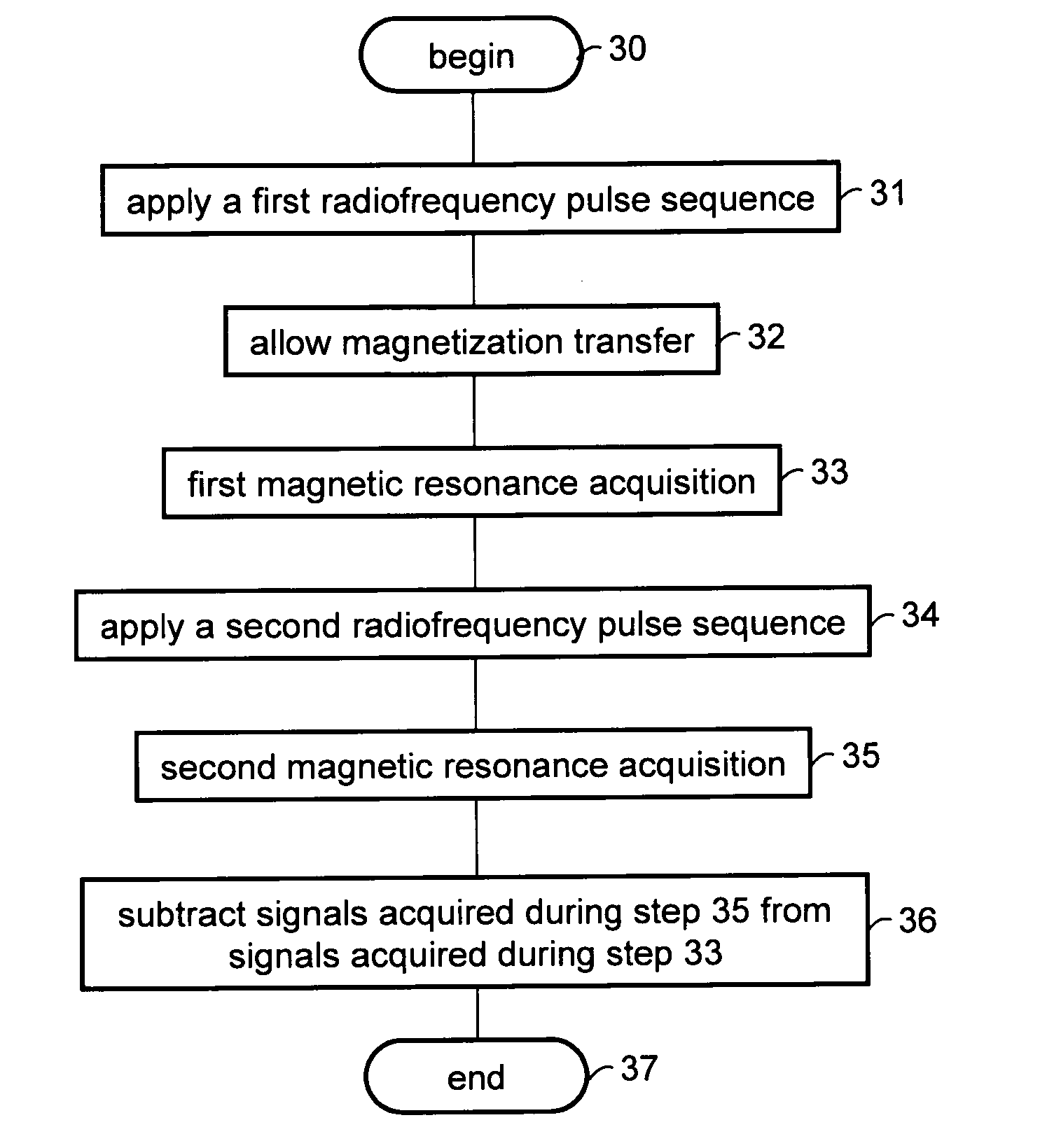
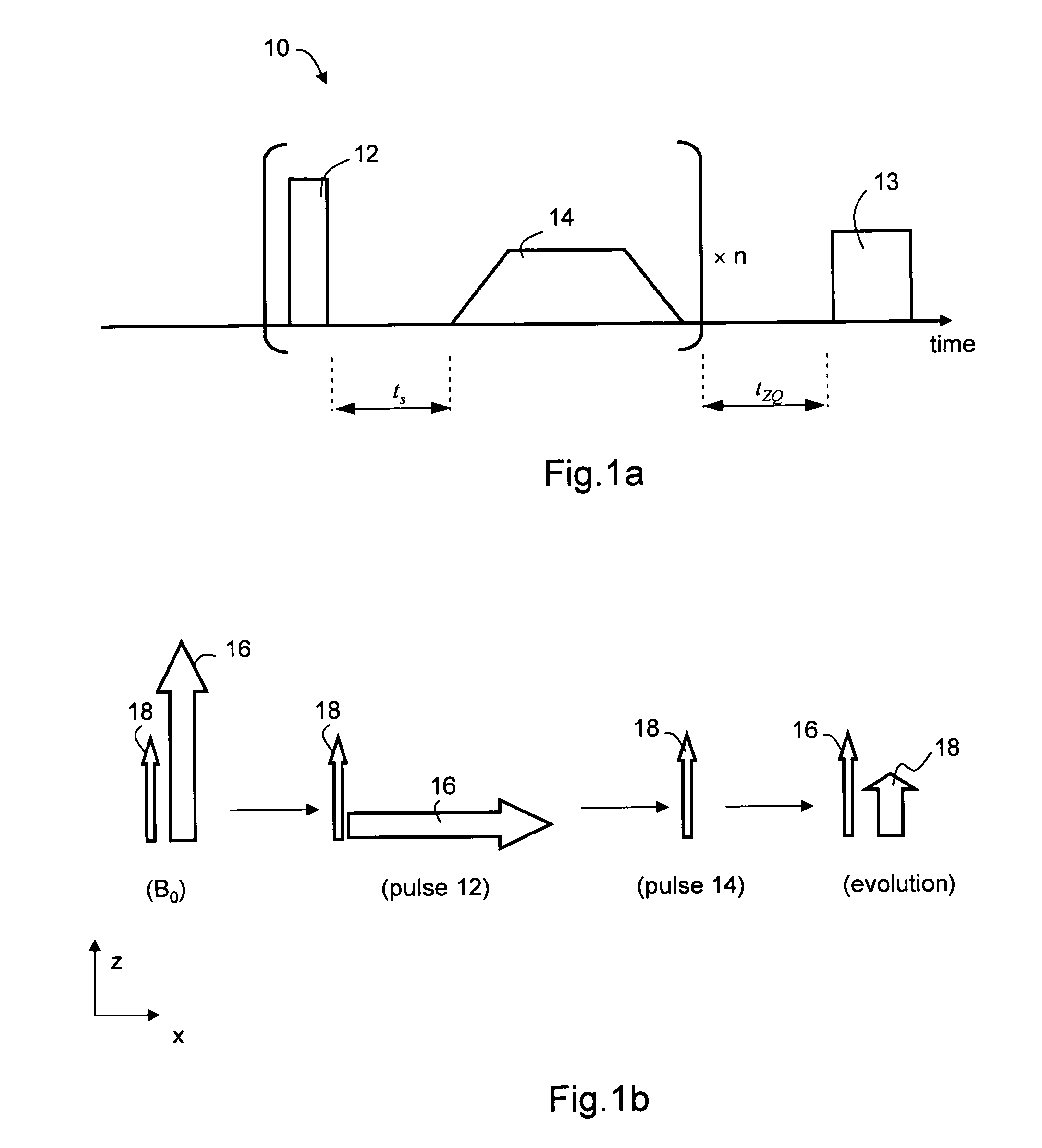
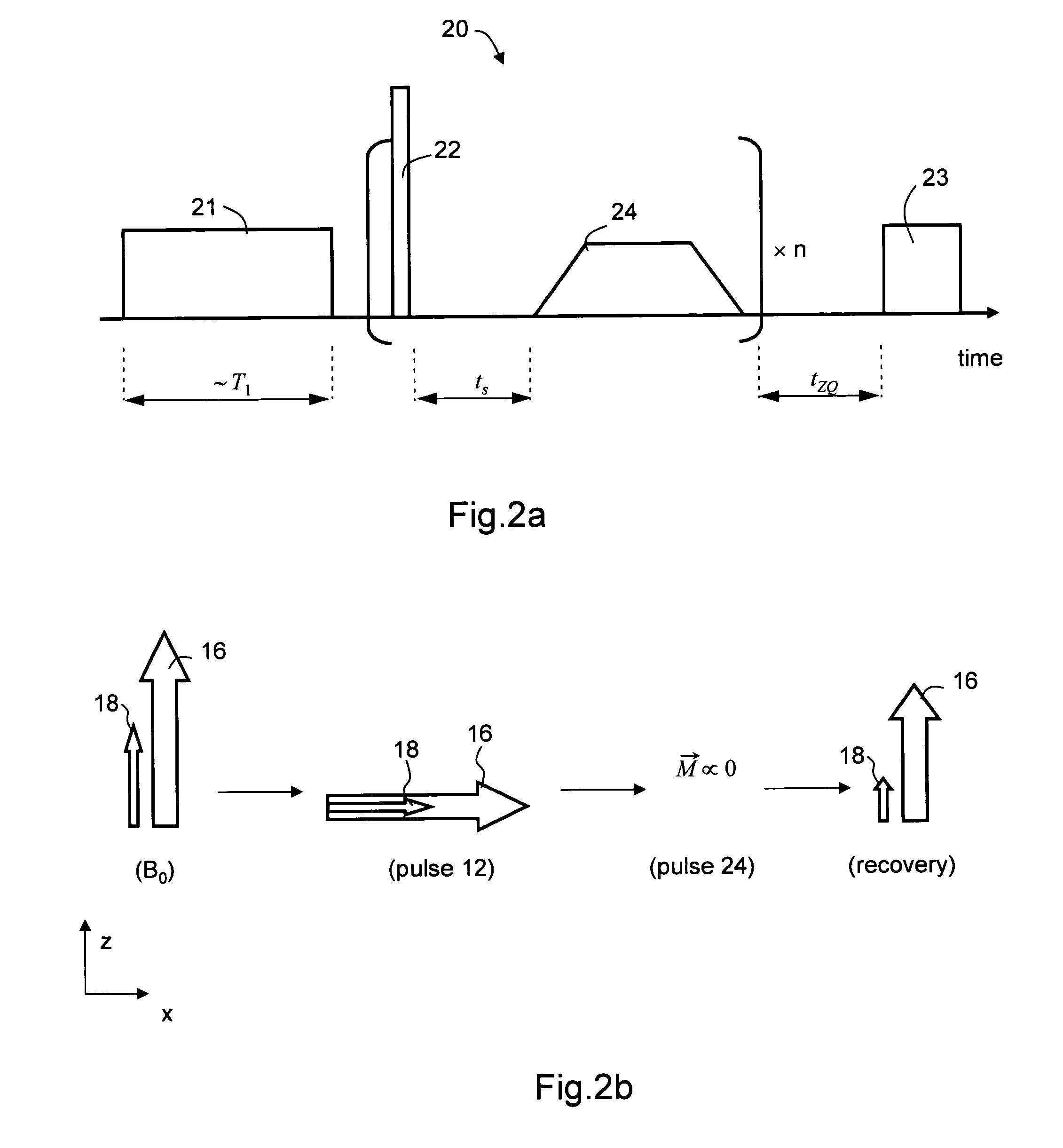
[0101]Experiments were performed on a 8.47 T WB 360 MHz Bruker micro-imager. The repetition factor was n=4. Signals acquired after longitudinal relaxation obtained using pulse sequence 20 were subtracted from signals acquired after magnetization transfer obtained using pulse sequence 10. The period tZQ was varied and a magnetization transfer rate was calculated. The lengths of the 90° pulses were 460 μs for sequence 10 and 120 μs for sequence 20. Two measurements were also made with pulses of 120 μs and without subtraction.

[0102]The imaging sequence used was a multi-spin echo (TSE factor=4, TE / TR=6 / 3500 ms). Data matrix: 128×128, FOV of 10 mm in plane and a slice thickness of 1 mm. The sequence was tested on mice models.

Results

[0103]FIGS. 5a-c are images obtained in accordance with the present embodiment by subtracting signals acquired after pulse sequence 20 from signals acquired after pulse sequence 10. Shown in FIGS. 5a-c are images obtained for three values ...

example 2

Materials and Methods

[0108]Experiments were performed on a 3T Philips Intera scanner. The repetition factor was n=8. The evolution period tZQ was varied and a magnetization transfer rate was calculated.

[0109]The imaging sequence used was a RARE (TSE factor=15, TE / TR=80 / 4000 ms). Data matrix: 128×128, FOV of 230 mm in plane and a slice thickness of 5 mm. The sequence was tested on a healthy volunteer using a transmit / receive head coil. Signals acquired after non-coherent longitudinal relaxation obtained using pulse sequence 20 were subtracted from signals acquired after magnetization coherence obtained using pulse sequence 10. The pulse lengths were 700 μs for pulse sequence 10 and 200 μs for pulse sequence 20.

Results

[0110]FIG. 6a shows a T2 weighted image of the axial slice on which the experiment was carried out. Two regions of interest (ROIs) on which the preliminary ROI analysis was carried out are marked with ellipses: one ROI is centered on a white matter region, and the other ...


PUM


Abstract

A method of magnetic resonance analysis of a body having therein at least one molecular species and water is disclosed. The method comprises, subtracting magnetic resonance signals induced by a second radiofrequency pulse sequence from magnetic resonance signals induced by a first radiofrequency pulse sequence followed by a evolution period. The first radiofrequency pulse sequence is selected so as to suppress magnetization for the water while preserving a generally longitudinal magnetization to the at least one molecular species. The second radiofrequency pulse sequence being selected so as to suppress transverse and longitudinal magnetization for both the water and the at least one molecular species.

Description

FIELD AND BACKGROUND OF THE INVENTION[0001]The present invention relates to magnetic resonance and, more particularly, to a method, system and radiofrequency pulse sequence for magnetic resonance analysis and / or imaging of a body having therein water molecules and one or more molecular species capable of magnetically interacting with the water molecules.[0002]Magnetic resonance imaging (MRI) is a method to obtain an image representing the chemical and physical microscopic properties of materials, by utilizing a quantum mechanical phenomenon, named Nuclear Magnetic Resonance (NMR), in which a system of spins, placed in a magnetic field resonantly absorb energy, when applied with a certain frequency.[0003]A nucleus can experience NMR only if its nuclear spin I does not vanish, i.e., the nucleus has at least one unpaired nucleon. Examples of non-zero spin nuclei frequently used in MRI include 1H (I=1 / 2), 2H (I=1), 23Na (I=3 / 2), etc. When placed in a magnetic field, a nucleus having a s...

Claims


Application Information

Patent Timeline
IPC IPC(8): G01R33/48
CPCG01R33/4828G01R33/5607G01R33/5605
Inventor ELIAV, UZINAVON, GILNEUFELD, ARNON
Owner RAMOT AT TEL AVIV UNIV LTD
Why Eureka
Try Eureka