Method and Configuration for the Optical Detection of an Illuminated Specimen

Active Publication Date: 2009-07-02
CARL ZEISS MICROSCOPY GMBH
View PDF2 Cites 47 Cited by
  • Summary
  • Abstract
  • Description
  • Claims
  • Application Information

AI Technical Summary

Benefits of technology

[0006]The invention relates to the implementation of a structured illumination method. Compared to the prior art, the proposed configuration has been simplified and can offer the advantage of making a high scanning speed possible. In addition, in developing the invention, the precision of the phase shift of the periodic structure is no longer critically dependent on the precision of the final control elements. The precisio

Problems solved by technology

An inaccurate shift of the projected structure can

Method used


Image

  • Method and Configuration for the Optical Detection of an Illuminated Specimen
  • Method and Configuration for the Optical Detection of an Illuminated Specimen
  • Method and Configuration for the Optical Detection of an Illuminated Specimen

Examples


Embodiment Construction

[0034]The invention will now be explained in detail based on practical examples.

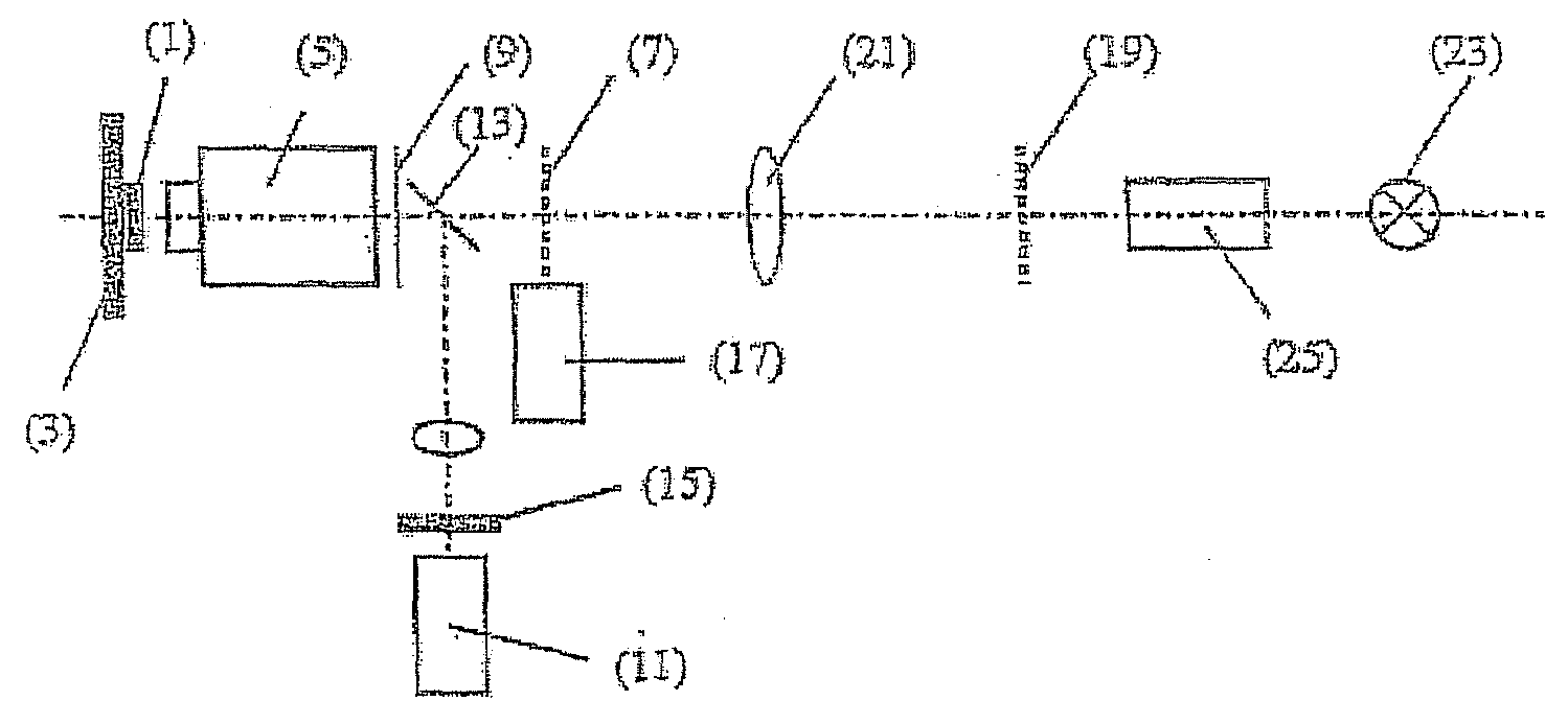
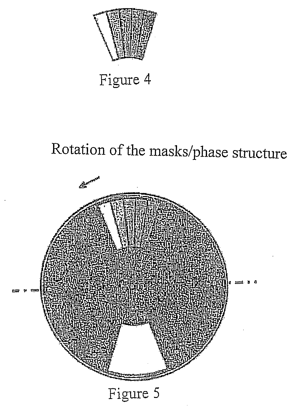
[0035]FIG. 1 shows a structure (phase structure, honeycomb structure) that is disposed in an intermediate image plane conjugate to the specimen, in this case, with an N=6-fold symmetry. The circular ring marks the illumination.

[0036]The structure shown in FIG. 1 generates a diffraction pattern in the pupil, again with a 6-fold symmetry of the diffraction orders, with oppositely lying pairs of the illumination corresponding to the orientation of one structure in one spatial direction.

[0037]A typical illumination distribution in the pupil of the objective lens or in a plane conjugate to said pupil is shown in FIG. 2. The light distribution generated by the structure shown in FIG. 1 in the pupil is illustrated. The points P drawn in are the sites of the diffraction orders, and the ring R shows the boundary of the pupil. The 0th diffraction order is preferably located on the optical axis OA. Given an N=6-fol...


PUM


Abstract

A method for the optical detection of an illuminated specimen, wherein the illuminating light impinges in a spatially structured manner in at least one plane on the specimen and several images of the specimen are acquired by a detector in different positions of the structure on the specimen, from which images an optical sectional image and/or an image with enhanced resolution is calculated. The method includes generating a diffraction pattern in the direction of the specimen in or near the pupil of the objective lens or in a plane conjugate to the pupil. A structured phase plate with regions of varying phase delays is dedicated to the diffraction pattern in or near the pupil of the objective lens or in a plane conjugate to said pupil. The phase plate is moved in order to set different phase angles of the illuminating light for at least one diffraction order on the specimen, wherein diffraction orders are selected to advantage via a movable diaphragm which is disposed in or near the pupil of the objective lens or in a plane conjugate to said pupil.

Description

CROSS REFERENCE[0001]This application claims the benefit of U.S. provisional patent application Ser. No. 60 / 990,007 filed on Nov. 26, 2007, the contents of which are hereby incorporated by reference herein.FIELD OF THE INVENTION[0002]The present invention relates generally to the field of microscopy, and more particularly to microscopy in which structured illumination is used for depth discrimination in the wide field and for enhancing resolution and contrast.BACKGROUND OF THE INVENTION[0003]In microscopy, structured illumination is used for depth discrimination in the wide field [1]1 and for enhancing the resolution and the contrast [2]. Generally, a grating or another periodic structure is projected into the specimen [3] or an interference pattern is generated in the specimen by means of interference of coherent component beams [4]. Subsequently, images that differ from one another due to the shift of the illumination structure are suitably blended with one another so as to obtain...

Claims


Application Information

Patent Timeline
IPC IPC(8): G02B21/06
CPCG02B21/0024G02B21/06G02B21/14
Inventor SCHWERTNER, MICHAELWOLLESCHENSKY, RALFKEMPE, MICHAEL
Owner CARL ZEISS MICROSCOPY GMBH
Why Eureka
Try Eureka