Line scanning CCD camera image correction method based on rotary carrying table and medium

An image correction and line scan technology, applied in image analysis, image data processing, graphic image conversion, etc., can solve problems such as the improvement of factory efficiency, the increase of weak defects, and the economy of missed inspection manufacturers, so as to improve efficiency and shorten the The effect of production time

Active Publication Date: 2020-08-04
WUHAN JINGLI ELECTRONICS TECH +1
View PDF7 Cites 0 Cited by
  • Summary
  • Abstract
  • Description
  • Claims
  • Application Information

AI Technical Summary

Problems solved by technology

[0007] like figure 1 As shown, the existing inspection process of the rotating stage is generally that the object to be inspected is carried on the rotating stage and rotated to the inspection station, and the area array camera is notified to take the image. improve
In addition, with the development trend of some electronic products, such as display screens / panels, towards large screens and thinner panels, the probability of weak defects is greatly increased. inspection and cause economic loss to the manufacturer

Method used


Image

  • Line scanning CCD camera image correction method based on rotary carrying table and medium
  • Line scanning CCD camera image correction method based on rotary carrying table and medium
  • Line scanning CCD camera image correction method based on rotary carrying table and medium

Examples


Embodiment approach

[0044] According to one embodiment of the present invention, a method for correcting images of a line-scan CCD camera based on a rotating stage is provided, including:

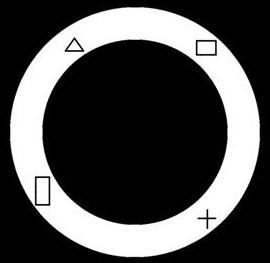
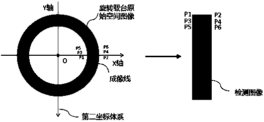
[0045] S1: The rotating stage drives the detection object to rotate. The line-scan CCD camera is located above the rotating stage and the extension line of its imaging line passes through the center of the rotating stage. A detection image of the detection object;

[0046] Further, the scanning area of ​​the line-scan CCD camera is an annular area;

[0047] S2: Establish a first coordinate system with the detection image, and obtain the first coordinate value and gray value of each pixel of the detection object in the first coordinate system;

[0048] S3: Establish a second coordinate system with a circular area, and obtain the second coordinate value of each pixel of the detection object in the second coordinate system; S4: Combine the first coordinate value in the first coordinate system with the first coor...


PUM


Abstract

The invention provides a line scanning CCD camera image correction method based on a rotary carrying platform and a medium. The method comprises the steps: enabling a rotary carrying table to drive adetection object to rotate, wherein a line scanning CCD camera is located above the rotary carrying table, an imaging line extension line of the line scanning CCD camera passes through the circle center of the rotary carrying table, and the line scanning CCD camera performs image acquisition on the detection object to generate a detection image of the detection object; establishing a first coordinate system by using the detection image, and obtaining a first coordinate value and a gray value of each pixel point of the detection object in the first coordinate system; establishing a second coordinate system by using the annular region, and obtaining a second coordinate value of each pixel point of the detection object in the second coordinate system; matching the first coordinate value in the first coordinate system with the second coordinate value in the second coordinate system, and establishing a coordinate mapping relationship; and converting the obtained detection image into an original space image on the rotary carrying platform according to the coordinate mapping relation. By means of the correction method, the limitation of a traditional area-array camera can be successfullyavoided, and meanwhile the benefit is greatly improved.

Description

technical field [0001] The technology mainly relates to the field of image data processing of automatic detection, in particular to an image correction method of a line-scan CCD camera based on a rotating stage. Background technique [0002] In the production and testing process of existing products, due to the influence of various factors such as environment, equipment and people, that is, cutting, cleaning, laminating, coating, transportation and other links may cause damage to the product. Compared with manual inspection, AOI defect detection has been gradually deployed in each station of panel production due to its fast detection speed and no influence of subjective factors, and has become an important link in factory quality management. [0003] In some specific areas of the factory, due to the constraints of the site area, the line body of the inspection station cannot be arranged in a straight line, so it needs to be designed as a rotating stage inspection mode. At p...

Claims


Application Information

Patent Timeline
Patent Type & Authority Applications(China)
IPC IPC(8): G06T7/80G06T3/40
CPCG06T3/4038G06T7/80G06T2200/32
Inventor 梁晓捷
Owner WUHAN JINGLI ELECTRONICS TECH
Why Eureka
Try Eureka