CMOS TDI sensor
An oxide semiconductor and time-delay technology, applied in the direction of TV, color TV parts, TV system parts, etc., can solve the problem of reducing the service life and avoid X-ray radiation damage
- Summary
- Abstract
- Description
- Claims
- Application Information
AI Technical Summary
Problems solved by technology
Method used
Image
Examples
Embodiment Construction
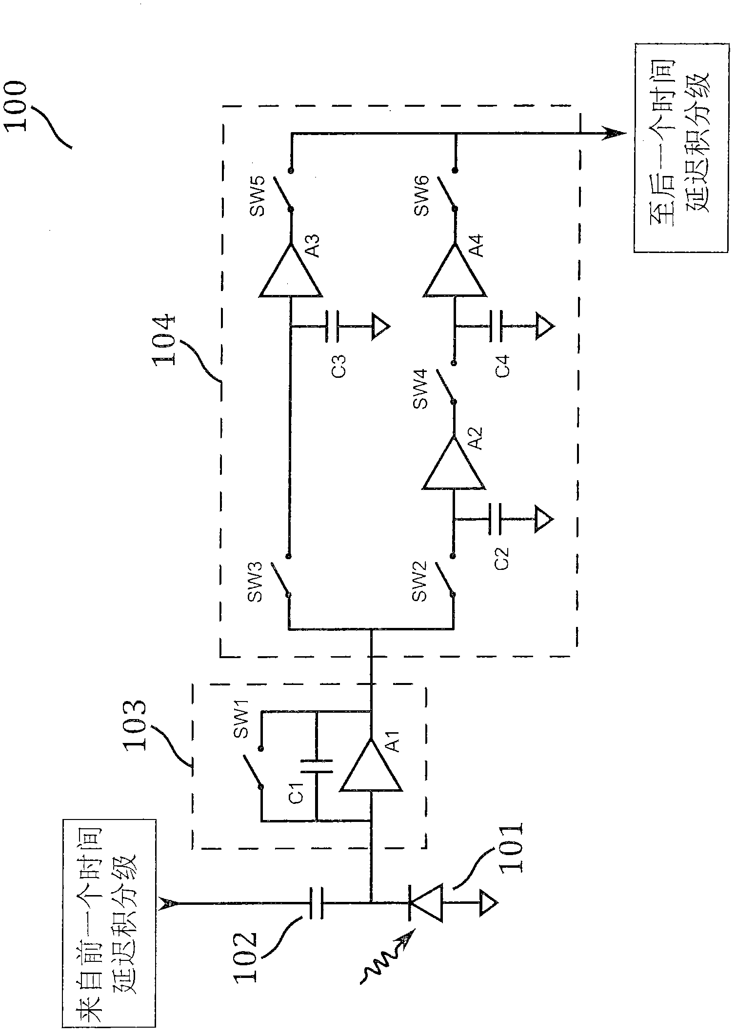
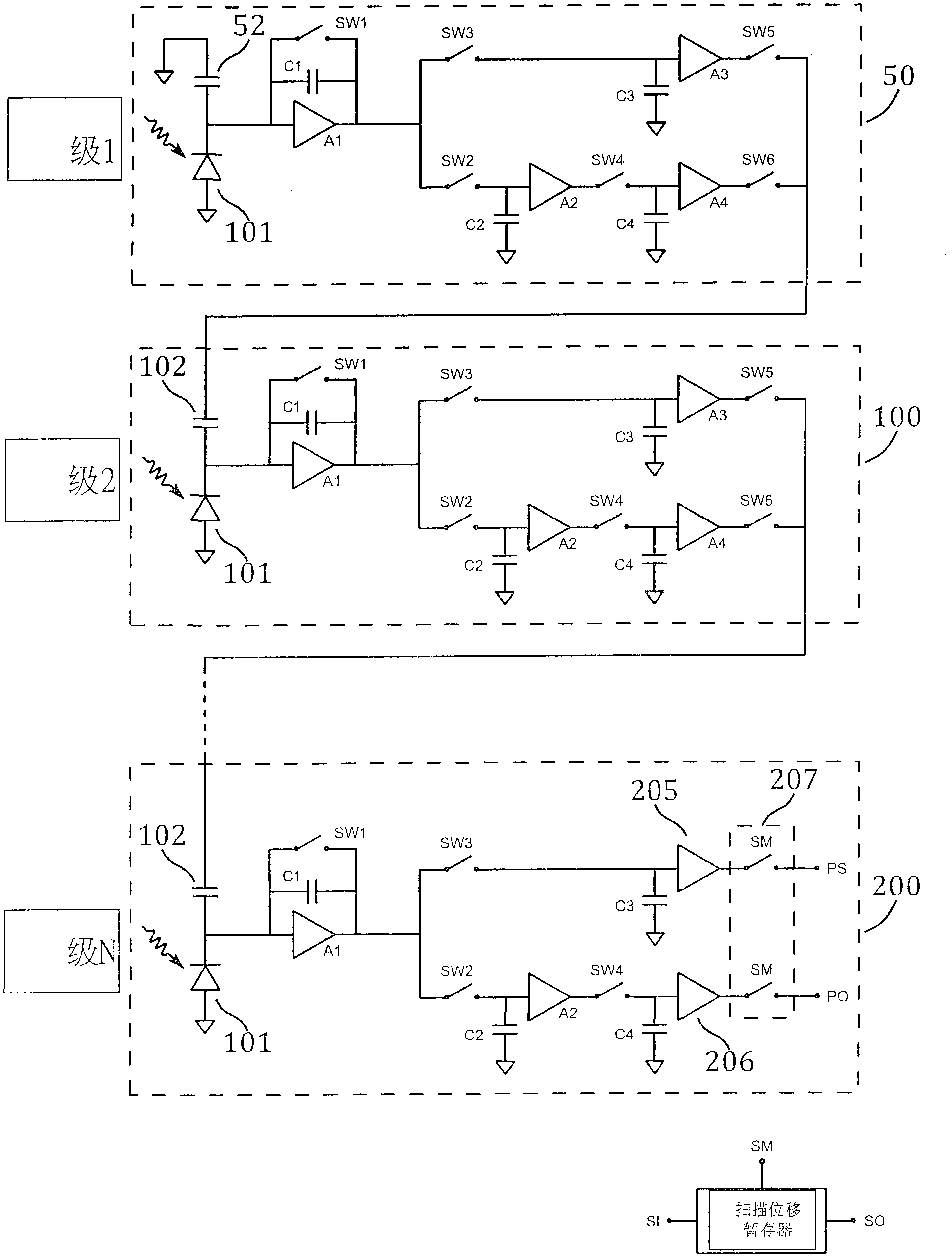
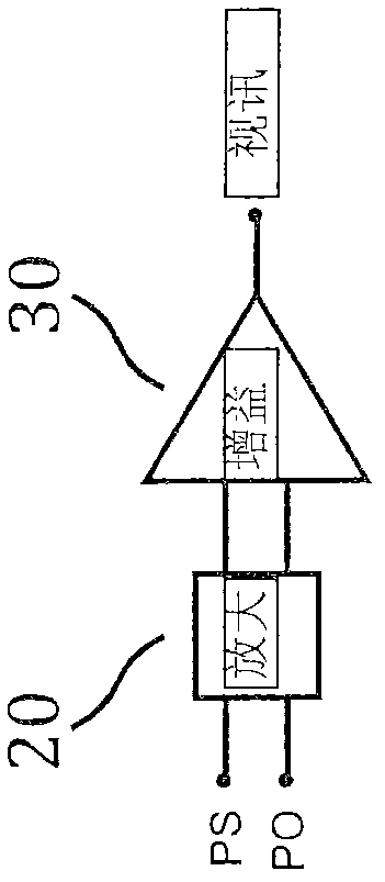
[0023] Figure 1 to Figure 4 A preferred embodiment of the present invention will be described. figure 1 A circuit diagram of a time delay and integrate (TDI) stage 100 is shown. figure 2 A circuit diagram showing a pixel of a linear detector with N time delay and integration stages. For an M pixel array, it includes M rows of circuits, as in figure 2 displayed in . image 3 Block diagram showing the correlated double sample and hold difference amplifier for reading the signal at the final time delay and integration stage. Figure 4 Timing diagrams are shown for operating time-delayed and integrating sensors.
[0024] as in figure 1As shown in , each time delay and integration stage 100 includes: a photodiode 101 , a summing capacitor 102 , an integrating and summing amplifier 103 , and a correlated double sampling and holding circuit 104 . The integrating and summing amplifier 103 includes: an amplifier A1, an integrating capacitor C1, and a reset switch SW1. An inte...
PUM
 Abstract
Description
Claims
Application Information
 - R&D
- Intellectual Property
- Life Sciences
- Materials
- Tech Scout
- Unparalleled Data Quality
- Higher Quality Content
- 60% Fewer Hallucinations
Browse by: Latest US Patents, China's latest patents, Technical Efficacy Thesaurus, Application Domain, Technology Topic, Popular Technical Reports.
© 2025 PatSnap. All rights reserved.Legal|Privacy policy|Modern Slavery Act Transparency Statement|Sitemap|About US| Contact US: help@patsnap.com


