Backlight unit

a backlight unit and backlight technology, applied in the field of backlight units, can solve the problems of complicated rework process limit in miniaturization and portability, and difficulty in reducing the size and thickness of the display device using the backlight unit, so as to achieve the effect of reducing the size and thickness of the backlight uni

Active Publication Date: 2009-07-02
SAMSUNG ELECTRONICS CO LTD
View PDF31 Cites 45 Cited by
  • Summary
  • Abstract
  • Description
  • Claims
  • Application Information

AI Technical Summary

Benefits of technology

[0015]An advantage of the present invention is that it provides a backlight unit in which an LED module, an optical sheet positioned above the LED module, and a heat radiating pad positioned under the LED module are integrally formed, thereby reducing the size and thickness of the backlight unit.
[0016]Additional aspects and advantages of the present general inventive concept will be set forth in part in the description which follows and, in part, will be obvious from the description, or may be learned by practice of the general inventive concept.
[0017]According to an aspect of the invention, a backlight unit comprises a plurality of light emitting diodes (LEDs) that emit light; a plurality of LED modules having a printed circuit board (PCB) which supports and drives the plurality of LEDs; a plurality of optical sheets that are attached to the top surfaces of the respective LED modules; and a plurality of heat radiating pads that are attached to the rear surfaces of the respective LED modules.
[0018]The optical sheet, and the heat radiating pad may be formed to have the same size.
[0019]The optical sheet and the heat radiating pad may have a smaller size than the LED module.
[0020]The LED modules may be arranged in parallel to each other in the longitudinal direction thereof.

Problems solved by technology

Cathode ray tubes (CRT), which are still used for information display devices, have many advantages in terms of performance and price, but have a limit in miniaturization and portability.
However, when the optical sheet of the backlight unit is formed so as to be spaced from the LED modules, there are difficulties in achieving a reduction in size and thickness of a display device using the backlight unit.
Therefore, a rework process of the backlight unit becomes complicated.

Method used


Image

  • Backlight unit
  • Backlight unit
  • Backlight unit

Examples


first embodiment

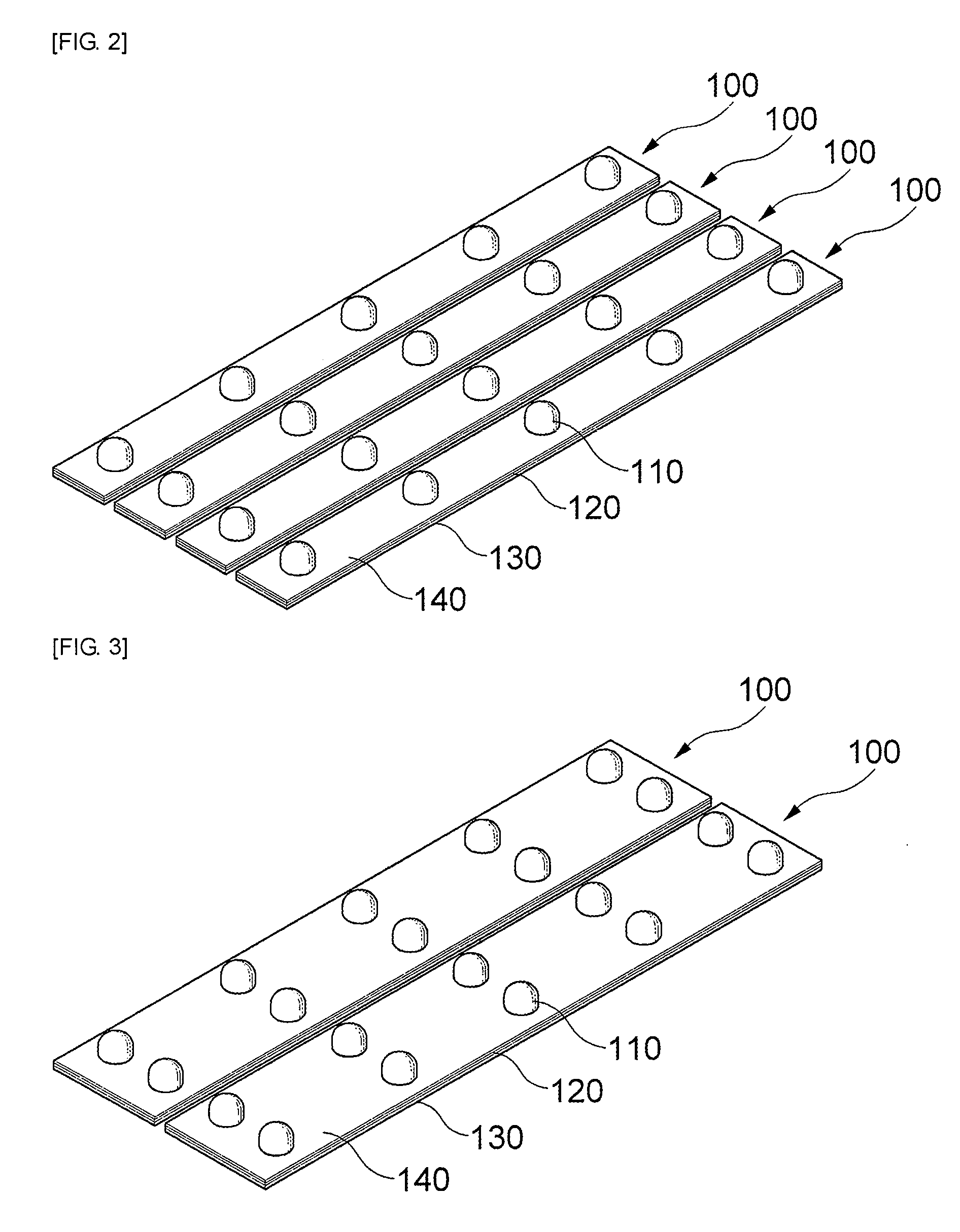
[0070]FIG. 3 is a perspective view showing the arrangement of a plurality of LEDs in a backlight unit according to the invention.

[0071]As shown in FIG. 3, the plurality of LEDs 110 may be arranged in two lines on one LED module 120. That is, the plurality of LEDs 110 may be arranged in one or more lines on one LED module 120 depending on the characteristic of the backlight unit.

second embodiment

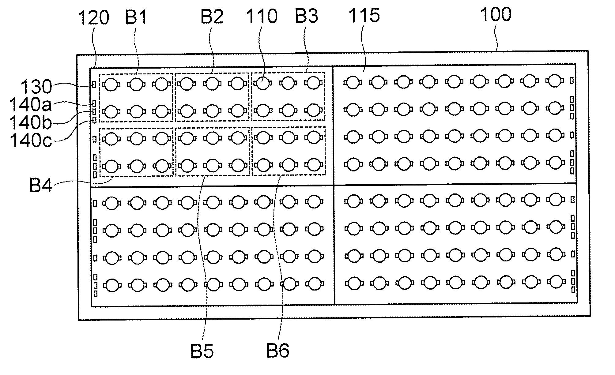
[0072]FIG. 4 is a plan view showing the arrangement of a plurality of blocks in a backlight unit according to the invention.

[0073]FIG. 5 is a plan view showing the arrangement of a plurality of LEDs in the backlight unit according to the second embodiment of the invention.

[0074]As shown in FIG. 4, a plurality of LEDs 110 may be continuously arranged on the LED module 120 so as to have a triangle shape. The plurality of LEDs 110 may be divided into a plurality of blocks A to D such that the backlight unit 100 is separately driven for each block. The respective blocks may be separated from each other so as to be independently turned on / off, and the LEDs disposed in each block are connected through printing circuit patterns. In this case, the heat radiating pad on the bottom surface of the LED module 120 may be omitted, if necessary, when a small amount of heat is generated.

[0075]By adjusting the arrangement of the LEDs, the backlight unit 100 can have optimal uniformity. As shown in F...

third embodiment

[0078]FIG. 6 is a plan view showing the arrangement of a plurality of blocks in a backlight unit according to the invention.

[0079]FIG. 7 is a plan view showing the arrangement of a plurality of LEDs in the backlight unit according to the third embodiment of the invention.

[0080]As shown in FIG. 6, the plurality of LEDs 110 on the LED module 120 may be continuously arranged in a square or rectangle, for example. The plurality of LEDs 110 may be divided into a plurality of blocks A to D such that the backlight unit is separately driven for each block. The respective blocks may be separated from each other so as to be independently turned on / off, and the LEDs disposed in each block are connected through printing circuit patterns. In this case, the heat radiating pad on the bottom surface of the LED module 120 may be omitted, if necessary, when a small amount of heat is generated.

[0081]As shown in FIG. 7, when the plurality of LEDs are arranged in a rectangle, the center luminous intensi...


PUM


Abstract

Provided is a backlight unit including a plurality of light emitting diodes (LEDs) that emit light; a plurality of LED modules having a printed circuit board (PCB) which supports and drives the plurality of LEDs; a plurality of optical sheets that are attached to the top surfaces of the respective LED modules; and a plurality of heat radiating pads that are attached to the rear surfaces of the respective LED modules.

Description

CROSS-REFERENCE TO RELATED APPLICATIONS[0001]This application is a Divisional of U.S. application Ser. No. 12 / 175,952, filed on Jul. 18, 2008, claims the benefit of Korean Patent Application Nos. 10-2007-0072266 and 10-2008-0069033 filed with the Korea Intellectual Property Office on Jul. 19, 2007 and Jul. 16, 2008, the disclosure of which is incorporated herein by reference.BACKGROUND OF THE INVENTION[0002]1. Field of the Invention[0003]The present invention relates to a backlight unit which uses light emitting diode (LED) modules.[0004]2. Description of the Related Art[0005]Recently, with the rapid development of semiconductor technology, the performance of products is further enhanced while the size and weight thereof is reduced. Cathode ray tubes (CRT), which are still used for information display devices, have many advantages in terms of performance and price, but have a limit in miniaturization and portability. As a device for overcoming such a disadvantage, a liquid crystal d...

Claims


Application Information

Patent Timeline
Patent Type & Authority Applications(United States)
IPC IPC(8): F21V9/16G09F13/04
CPCF21K9/00G02F1/133603G02F2001/133614H05K1/142F21K9/50G02F2001/133628F21K9/60G02F1/133628G02F1/133614
Inventor KIM, DAE YEONJEONG, YOUNG JUNEHAHM, HUN JOOSHIN, JAE HONGSHIN, CHANG HO
Owner SAMSUNG ELECTRONICS CO LTD
Why Eureka
Try Eureka