
Ultrasonic treatment chamber for particle dispersion into formulations

a technology of particle dispersion and treatment chamber, which is applied in the direction of mixing, transportation and packaging, chemical instruments and processes, etc., can solve the problems of human error, time, energy and money, and the method of mixing powders and particulates into formulations,

Active Publication Date: 2009-07-02
KIMBERLY-CLARK WORLDWIDE INC
View PDF96 Cites 44 Cited by
  • Summary
  • Abstract
  • Description
  • Claims
  • Application Information

AI Technical Summary

Benefits of technology

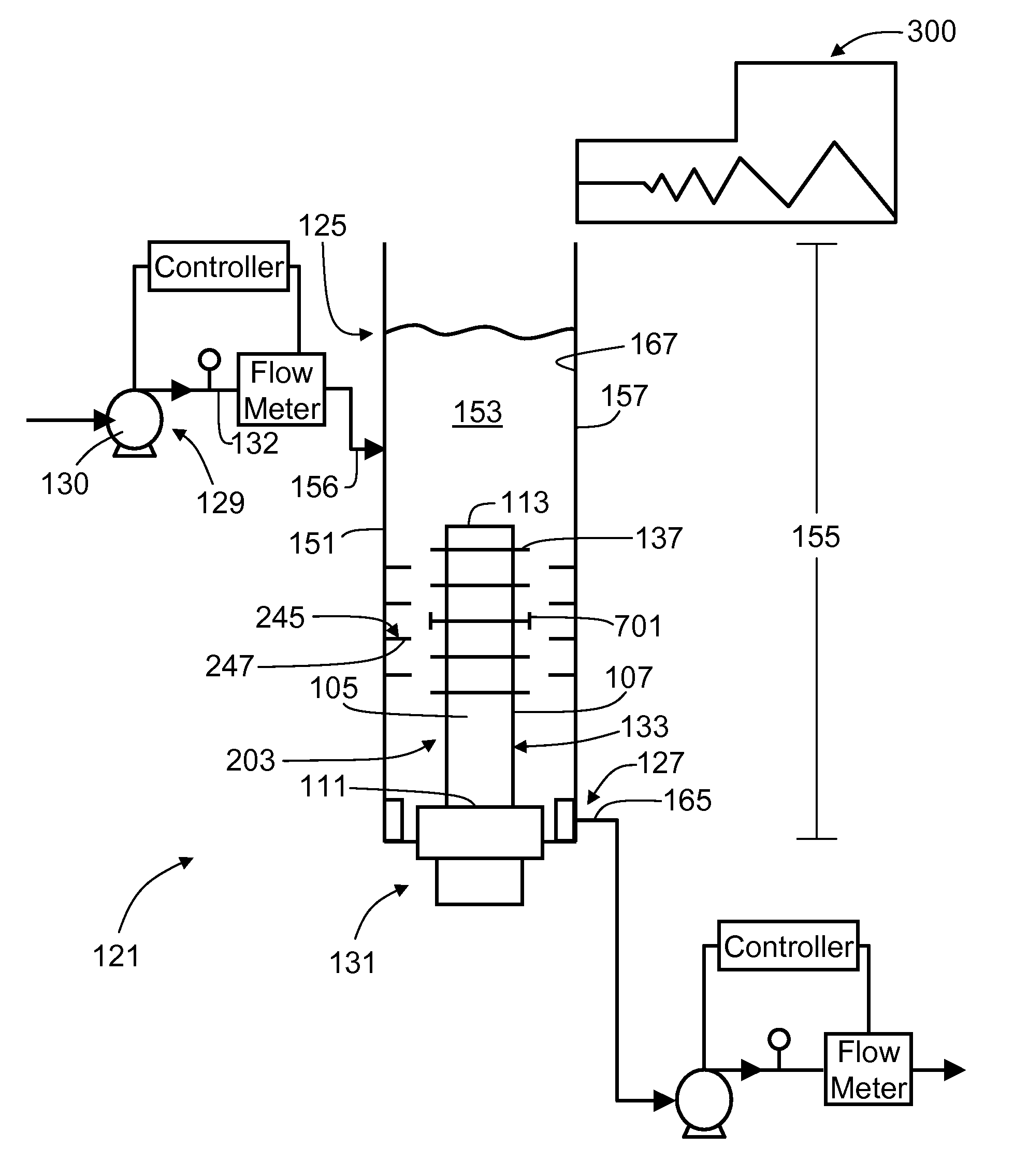
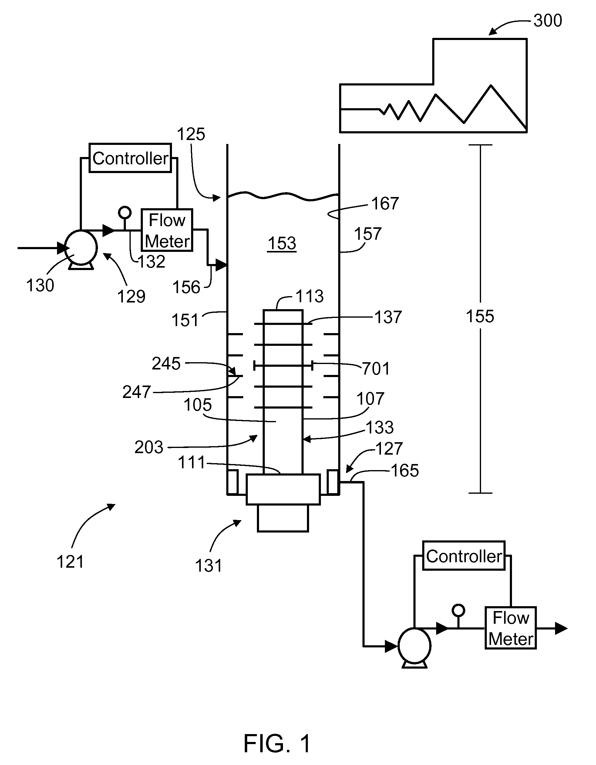
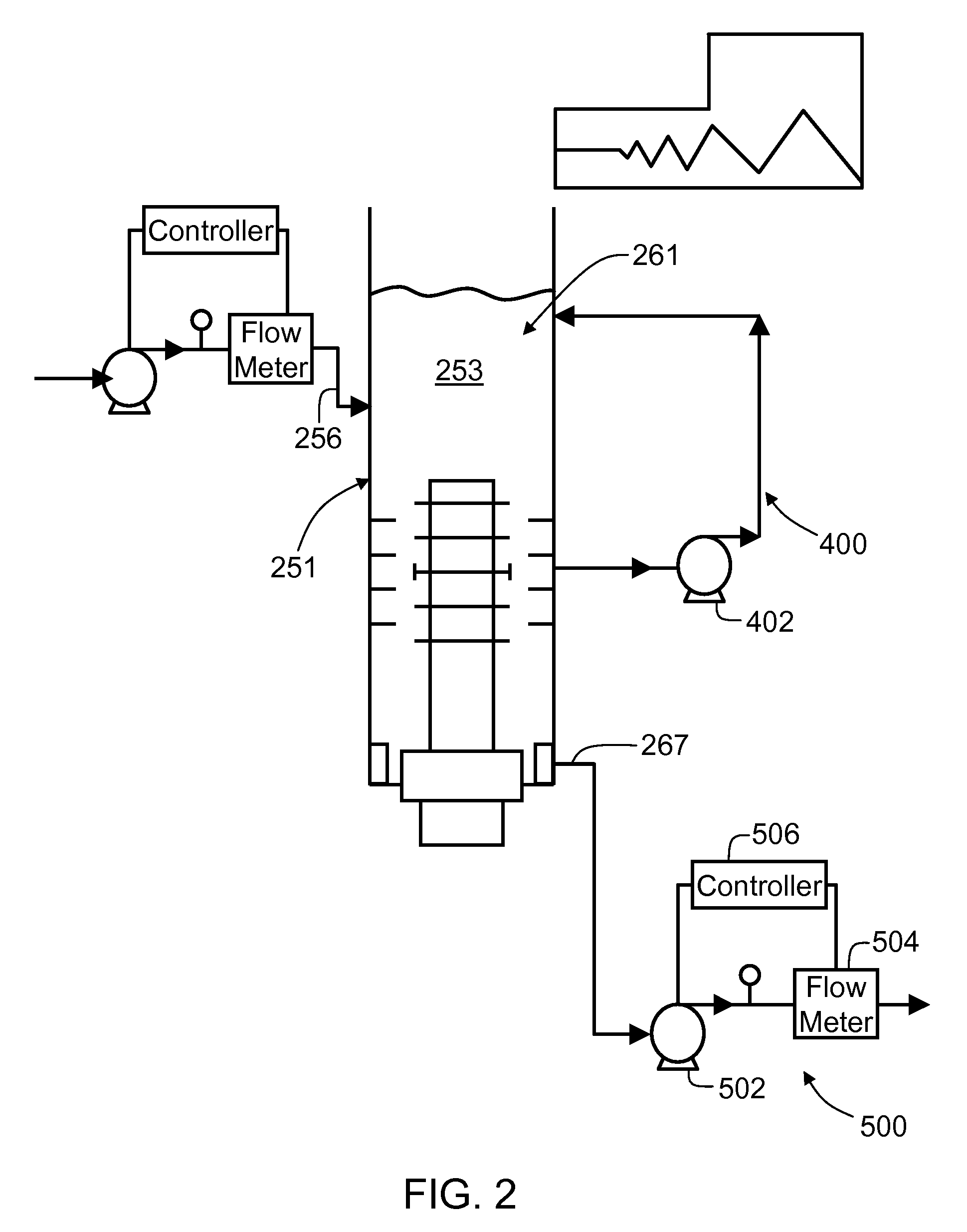
[0007]In one aspect, an ultrasonic mixing system for mixing particulates into a formulation generally comprises a treatment chamber comprising an elongate housing having longitudinally opposite ends and an interior space, and a particulate dispensing system for dispensing particulates into the treatment chamber. The housing of the treatment chamber is generally closed at at least one of its longitudinal ends and has at least one inlet port for receiving a formulation into the interior space of the housing and at least one outlet port through which a particulate-containing formulation is exhausted from the housing following ultrasonic mixing of the formulation and particulates. The outlet port is spaced longitudinally from the inlet port such that liquid flows longitudinally within the interior space of the housing from the inlet port to the outlet port. In one embodiment, the housing includes two separate ports for receiving separate components of the formulation. At least one elongate ultrasonic waveguide assembly extends longitudinally within the interior space of the housing and is operable at a predetermined ultrasonic frequency to ultrasonically energize and mix the formulation and the particulates flowing within the housing.
[0009]As such the present disclosure is directed to an ultrasonic mixing system for mixing particulates into a formulation. The mixing system comprises a treatment chamber and a particulate dispensing system capable of dispensing particulates into the treatment chamber for mixing with the formulation. The treatment chamber generally comprises an elongate housing having longitudinally opposite ends and an interior space, and an elongate ultrasonic waveguide assembly extending longitudinally within the interior space of the housing and being operable at a predetermined ultrasonic frequency to ultrasonically energize and mix the formulation and particulates flowing within the housing. The housing is generally closed at at least one of its longitudinal ends and has at least one inlet port for receiving a formulation into the interior space of the housing and at least one outlet port through which a particulate-containing formulation is exhausted from the housing following ultrasonic mixing of the formulation and particulates. The outlet port is spaced longitudinally from the inlet port such that liquid flows longitudinally within the interior space of the housing from the inlet port to the outlet port.
[0011]The present invention is further directed to an ultrasonic mixing system for mixing particulates into a formulation. The mixing system comprises a treatment chamber and a particulate dispensing system capable of dispensing particulates into the treatment chamber for mixing with the formulation. The treatment chamber generally comprises an elongate housing having longitudinally opposite ends and an interior space, and an elongate ultrasonic waveguide assembly extending longitudinally within the interior space of the housing and being operable at a predetermined ultrasonic frequency to ultrasonically energize and mix the formulation and particulates flowing within the housing. The housing is generally closed at at least one of its longitudinal ends and has at least one inlet port for receiving a formulation into the interior space of the housing and at least one outlet port through which a particulate-containing formulation is exhausted from the housing following ultrasonic mixing of the formulation and particulates. The outlet port is spaced longitudinally from the inlet port such that liquid flows longitudinally within the interior space of the housing from the inlet port to the outlet port.

Problems solved by technology

Although powders are useful, current mixing procedures have multiple problems such as dusting, clumping, and poor hydration, which can waste time, energy, and money for manufacturers of these formulations.
These conventional methods of mixing powders and particulates into formulations have several problems.
Prior to adding the ingredients, each needs to be weighed, which can create human error.
Specifically, as the ingredients need to be weighed one at a time, misweighing can occur with the additive amounts.
Furthermore, by manually adding the ingredients, there is a risk of spilling or of incomplete transfers of the ingredients from one container to the next.
One other major issue with conventional methods of mixing powders into formulations is that batching processes require heating times, mixing times, and additive times that are entirely manual and left up to the individual compounders to follow the instructions.
These practices can lead to inconsistencies from batch-to-batch and from compounder to compounder.
Furthermore, these procedures required several hours to complete, which can get extremely expensive.

Method used


Image

  • Ultrasonic treatment chamber for particle dispersion into formulations
  • Ultrasonic treatment chamber for particle dispersion into formulations
  • Ultrasonic treatment chamber for particle dispersion into formulations

Examples


example 1

[0087]In this Example, various particulates were mixed with tap water in the ultrasonic mixing system of FIG. 1 of the present disclosure. The ability of the ultrasonic mixing system to effectively mix the particulates into the water formulation to form a homogenous mixture was compared to manually stirring the mixture in a beaker. Additionally, the ability of the particulates to remain homogenously mixed with the water was analyzed and compared to the mixture produced using manual stirring in the beaker.

[0088]Each particulate-type was independently added to tap water and mixed using either the ultrasonic mixing system of FIG. 1 or a spatula manually stirring the liquid in a beaker. All samples of particulate-containing water were visually observed immediately after mixing, 10 minutes after mixing, 1 hour after mixing, 20 hours after mixing, and 30 hours after mixing. The various particulates, amounts of particulates, amount of tap water, and visual observations are shown in Table 3...


PUM

PropertyMeasurementUnit
Frequencyaaaaaaaaaa
Frequencyaaaaaaaaaa
Flow rateaaaaaaaaaa

Abstract

An ultrasonic mixing system having a particulate dispensing system to dispense particulates into a treatment chamber and the treatment chamber in which particulates can be mixed with one or more formulations is disclosed. Specifically, the treatment chamber has an elongate housing through which a formulation and particulates flow longitudinally from an inlet port to an outlet port thereof. An elongate ultrasonic waveguide assembly extends within the housing and is operable at a predetermined ultrasonic frequency to ultrasonically energize the formulation and particulates within the housing. An elongate ultrasonic horn of the waveguide assembly is disposed at least in part intermediate the inlet and outlet ports, and has a plurality of discrete agitating members in contact with and extending transversely outward from the horn intermediate the inlet and outlet ports in longitudinally spaced relationship with each other. The horn and agitating members are constructed and arranged for dynamic motion of the agitating members relative to the horn at the predetermined frequency and to operate in an ultrasonic cavitation mode of the agitating members corresponding to the predetermined frequency and the formulation and particulates being mixed in the chamber.

Description

FIELD OF DISCLOSURE[0001]The present disclosure relates generally to systems for ultrasonically mixing particulates into various formulations. More particularly an ultrasonic mixing system is disclosed for ultrasonically mixing particulates, typically in powder-form, into formulations such as cosmetic formulations.BACKGROUND OF DISCLOSURE[0002]Powders and particulates are commonly added to formulations such as cosmetic formulations to provide various benefits, including, for example, absorbing water, modifying feel, thickening the formulation, and / or protecting skin. Although powders are useful, current mixing procedures have multiple problems such as dusting, clumping, and poor hydration, which can waste time, energy, and money for manufacturers of these formulations.[0003]Specifically, formulations are currently prepared in a batch-type process, either by a cold mix or a hot mix procedure. The cold mix procedure generally consists of multiple ingredients or phases being added into...

Claims


Application Information

Patent Timeline
IPC IPC(8): B01F11/02B01F33/40
CPCB01F3/1242B01F5/10B01F2215/0454B01F2215/045B01F11/0258B01F23/551B01F25/50B01F31/85
Inventor WENZEL, SCOTT W.AHLES, JOHN GLENEHLERT, THOMAS DAVIDJANSSEN, ROBERT ALLENKOENIG, DAVID WILLIAMRASMUSSEN, PAUL WARRENROFFERS, STEVEZHUANG, SHIMING
Owner KIMBERLY-CLARK WORLDWIDE INC
Learn More