Optical disk apparatus, position control method, and optical pickup

a technology of optical disc and position control method, which is applied in the direction of optical recording/reproducing/erasing methods, instruments, disposition/mounting of heads, etc., can solve the problems of increasing the degree of warpage of the optical disk b>100/b>, and the warpage of the optical disk itself, so as to increase the positional accuracy of recording marks formed

Inactive Publication Date: 2009-07-02
SONY CORP
View PDF7 Cites 11 Cited by
  • Summary
  • Abstract
  • Description
  • Claims
  • Application Information

AI Technical Summary

Benefits of technology

[0022]The present invention has been made in view of the above points, and is intended to provide an optical disk apparatus, a position control method, and an optical pickup capable of increasing the positional accuracy of recording marks formed in a uniform recording layer of an optical disk.
[0024]With the above configuration, the optical disk apparatus according to the first aspect of the present invention can focus the information light beam onto a track away from the reference track by a distance corresponding to the total width of a predetermined number of tracks simply by focusing the focal point of the reference light beam onto the existing reference track.
[0026]With the above configuration, the position control method according to the second aspect of the present invention can focus the information light beam onto a track away from the reference track by a distance corresponding to the total width of a predetermined number of tracks simply by focusing the focal point of the reference light beam onto the existing reference track.
[0028]With the above configuration, the optical pickup according to the third aspect of the present invention can focus the information light beam onto a track away from the reference track by a distance corresponding to the total width of a predetermined number of tracks simply by focusing the focal point of the reference light beam onto the existing reference track using a predetermined position control section.
[0029]According to the present invention, it is possible to focus the information light beam onto a track away from the reference track by a distance corresponding to the total width of a predetermined number of tracks simply by focusing the focal point of the reference light beam onto the existing reference track. As a result, an optical disk apparatus and a position control method capable of increasing the positional accuracy of recording marks formed in a uniform recording layer of an optical disk can be realized.
[0030]Further, according to the present invention, it is possible to focus the information light beam onto a track away from the reference track by a distance corresponding to the total width of a predetermined number of tracks simply by focusing the focal point of the reference light beam onto the existing reference track using a predetermined position control section. As a result, an optical pickup capable of increasing the positional accuracy of recording marks formed in a uniform recording layer of an optical disk can be realized.

Problems solved by technology

However, in the optical disk apparatus, there is a possibility that the optical disk 100 is attached in an inclined manner, or there is a possibility that warpage of the optical disk 100 itself occurs.
Furthermore, there is a possibility that the degree of the warpage of the optical disk 100 gradually changes with age.

Method used


Image

  • Optical disk apparatus, position control method, and optical pickup
  • Optical disk apparatus, position control method, and optical pickup
  • Optical disk apparatus, position control method, and optical pickup

Examples


first embodiment

(1) First Embodiment

(1-1) Basic Principle of Focus Position Control

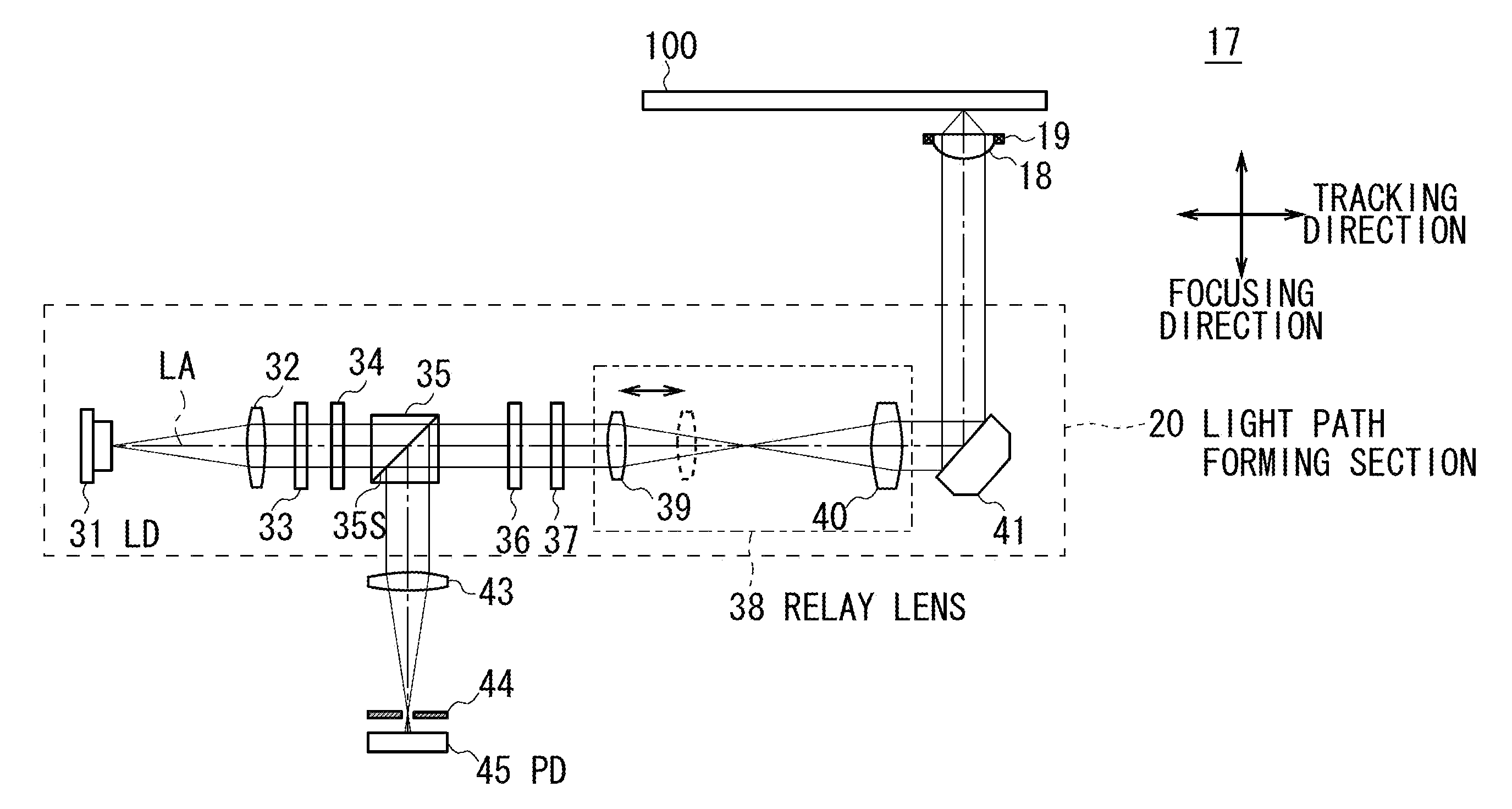
[0056]The basic principle of focus position control according to a first embodiment will be described. In the first embodiment, an optical disk apparatus 10 irradiates an optical disk 100 with an information light beam LM to record information in the optical disk 100 and detects a reflected information light beam LM which is the reflected light of the information light beam LM to read out information from the optical disk 100.

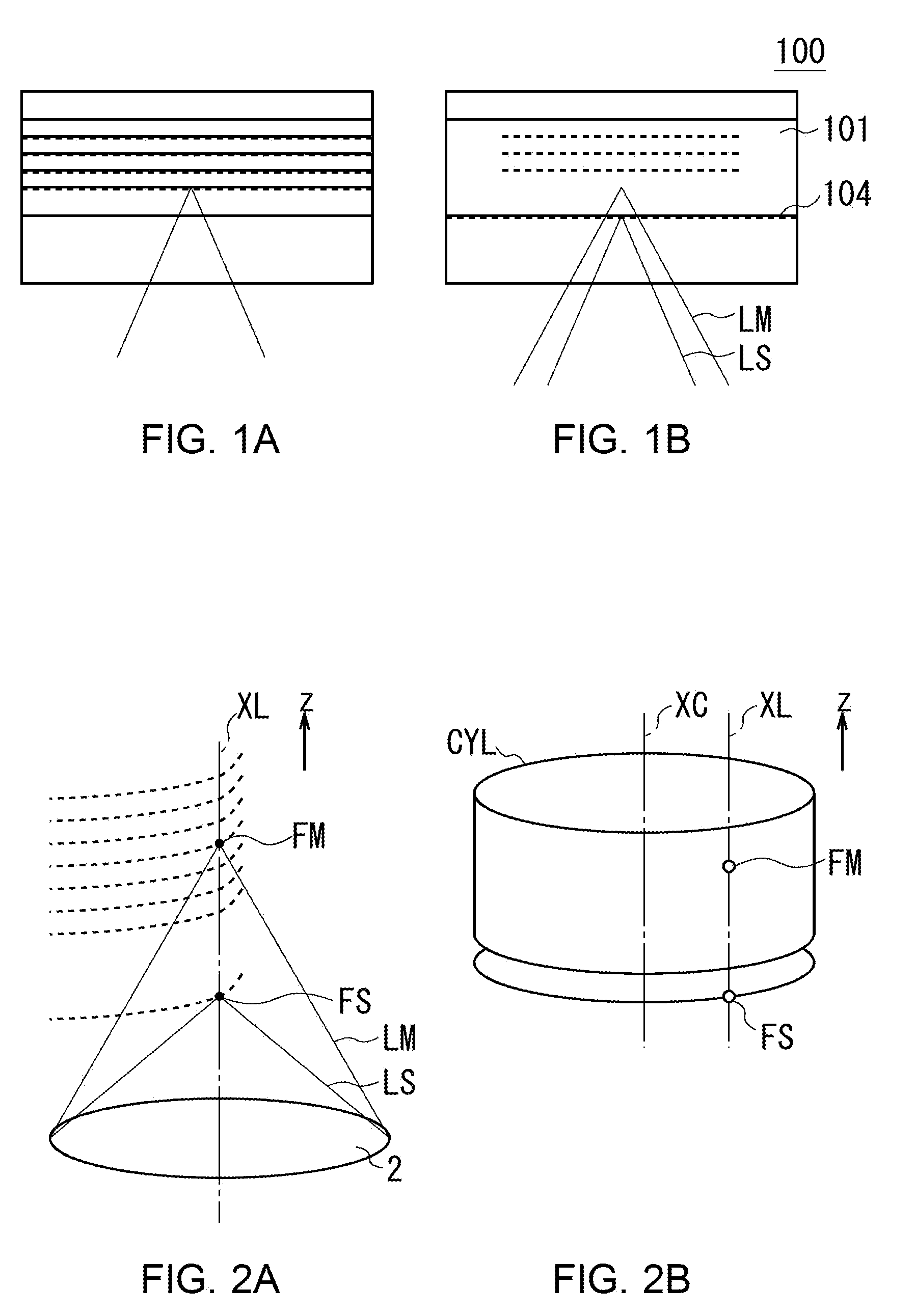
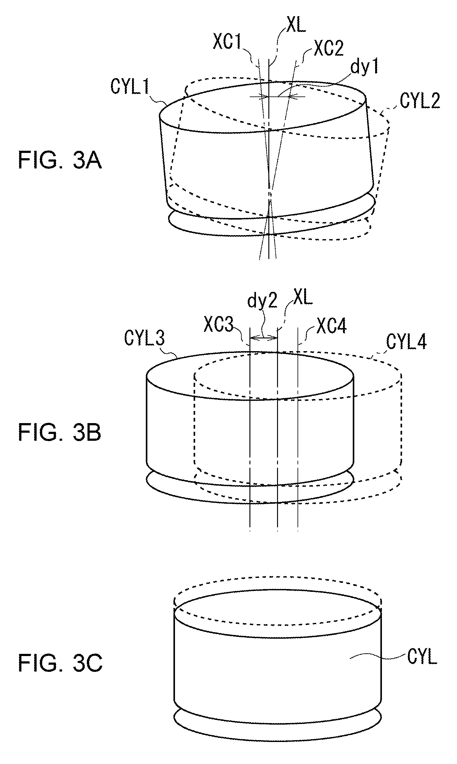
[0057]As shown in the external view of FIG. 5, the optical disk 100 is formed into substantially a disk shape as a whole and has a hole 100H for chucking provided in the center thereof. Further, as shown in the cross-sectional view of FIG. 6, the optical disk 100 has a structure in which a recording layer 100 for information recording is sandwiched between substrates 102 and 103.

[0058]The optical disk apparatus 10 condenses, using an objective lens 18, the information light beam LM emitted from ...

second embodiment

(2) Second Embodiment

(2-1) Basic Principle of Focus Position Control

[0170]The basic principle of focus position control according to a second embodiment will next be described. In the second embodiment, recording marks RM which are holograms are formed in the recording layer 201 of the optical disk 200 (corresponding to the recording layer 101 of the optical disk 100 in the first embodiment), as shown in FIG. 14 (corresponding to FIG. 6 of the first embodiment).

[0171]That is, when recording information in the optical disk 200, the optical disk apparatus 110 uses an objective lens 121 to condense an information light beam LM1 from the first surface 200A side and uses an objective lens 122 to condense an information light beam LM2 onto the same focal point FM1 as the information light beam LM1 from the other surface 200B side. In this case, the information light beam LM1 and information light beam LM2 are laser lights which are emitted from the same light source and are coherent with ...


PUM

PropertyMeasurementUnit
diameteraaaaaaaaaa
widthaaaaaaaaaa
total widthaaaaaaaaaa

Abstract

An optical disk apparatus appropriately adjusts the optical paths of a reference light beam and information light beam in an optical path forming section of an optical pickup, condenses the reference light beam and information light beam using an objective lens, and performs position control of the objective lens in the focusing and tracking directions so as to focus the reference light beam onto a reference track in a target mark layer, thereby focusing the focal point of the information light beam condensed by the objective lens onto a target track TG in the target mark layer.

Description

CROSS REFERENCES TO RELATED APPLICATIONS[0001]The present invention contains subject matter related to Japanese Patent Application JP2007-341371 filed in the Japanese Patent Office on Dec. 28, 2007, the entire contents of which being incorporated herein by reference.BACKGROUND OF THE INVENTION[0002]1. Field of the Invention[0003]The present invention relates to an optical disc apparatus, a position control method and an optical pickup. The present invention provides a technique that can suitably be applied to an optical disc apparatus for recording information on a plurality of layers of an optical disc.[0004]2. Description of the Related Art[0005]Known popular optical disc apparatus are mostly designed to irradiate a light beam on an optical disc such as a compact disc (CD), a digital versatile disc (DVD) or a Blu-ray disc (registered trademark, to be referred to as “BD” hereinafter) and reproduce information by reading the reflected light beam.[0006]Such known popular optical disc...

Claims


Application Information

Patent Timeline
Patent Type & Authority Applications(United States)
IPC IPC(8): G11B7/135
CPCG11B7/00452G11B2007/0013G11B7/1378G11B7/09G11B7/1374
Inventor MIYAMOTO, HIROTAKASAITO, KIMIHIROFUJITA, GORO
Owner SONY CORP
Why Eureka
Try Eureka