Mobile communication system, mobile station device, base station device, and mobile communication method

a mobile communication system and mobile station technology, applied in the field of mobile communication systems, can solve the problem that data transmission to/from the base station device cannot be executed on the mobile station device side, and achieve the effect of reducing gap generation processing and power consumption

Inactive Publication Date: 2009-07-02
SHARP KK
View PDF4 Cites 50 Cited by
  • Summary
  • Abstract
  • Description
  • Claims
  • Application Information

AI Technical Summary

Benefits of technology

[0046]In the mobile station device of the present invention, the first measuring unit measures a predetermined time, and the first generating unit generates a gap section when it is determined to monitor a peripheral base station device based on a channel quality indication, and then suspends generating another gap section from when the generation of the gap section is initiated to when the first measuring unit finishes measuring the predetermined time. In addition, in the base station device of the present invention, the second measuring unit measures a predetermined period, and the second generating unit that generates a gap section in which the base station device does n

Problems solved by technology

Also in HSDPA, when the monitoring or the measuring of the base station device utilizing the different frequency i

Method used


Image

  • Mobile communication system, mobile station device, base station device, and mobile communication method
  • Mobile communication system, mobile station device, base station device, and mobile communication method
  • Mobile communication system, mobile station device, base station device, and mobile communication method

Examples


first embodiment

[0092]A mobile communication system according to the present invention is explained.

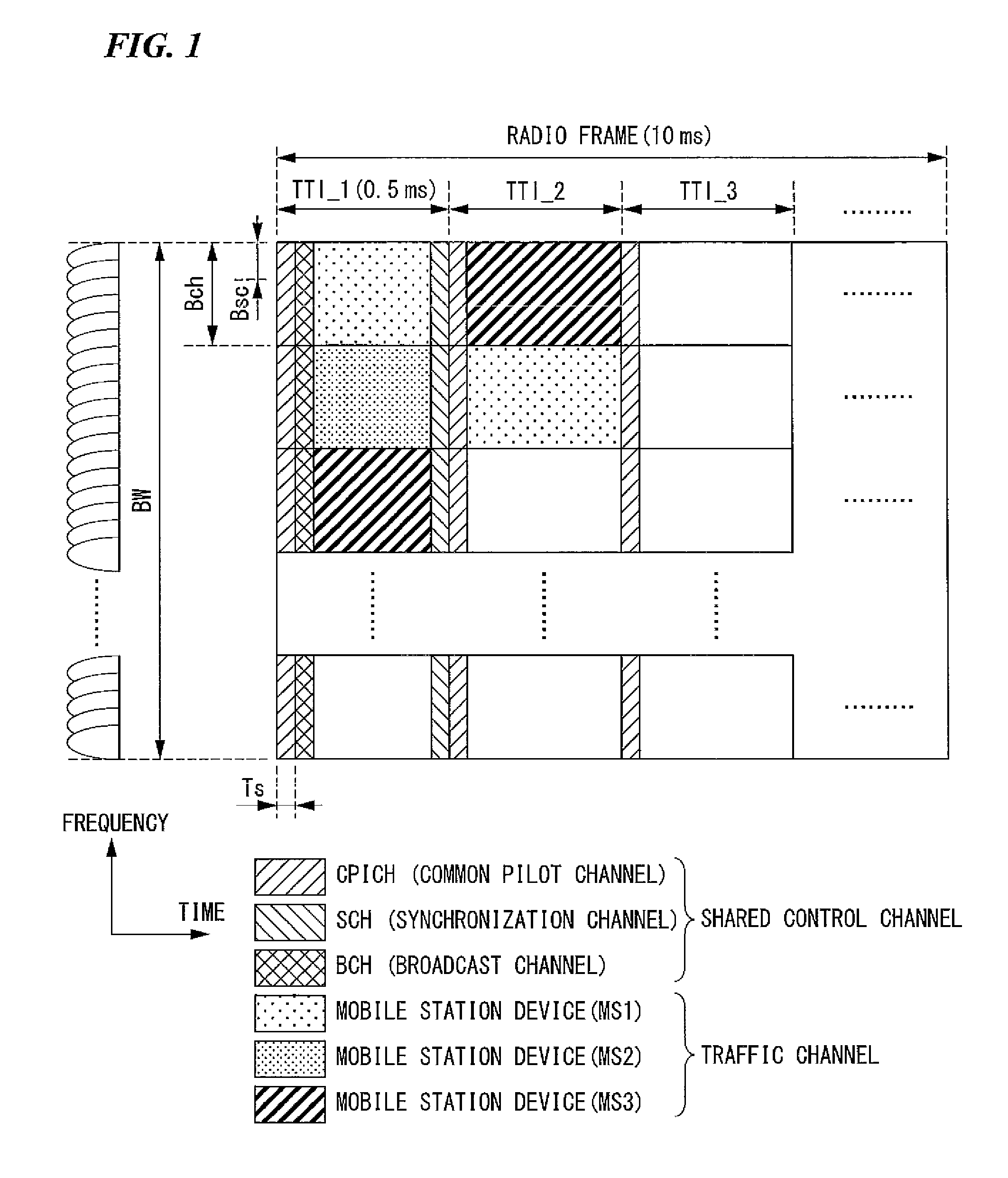
[0093]FIG. 1 is a schematic view showing an example of a radio frame configuration in E-UTRA downlink based on 3GPP. As shown in FIG. 1, the horizontal and the vertical axes indicate time and frequency, respectively. The downlink radio frame is a bundle of subcarriers, and includes two-dimensional radio RBs (resource blocks) defined by a frequency bandwidth Bch and a TTI (Transmission Timing Interval). BW, Bch, Bsc, and Ts represent a downlink frequency bandwidth, a resource-block frequency bandwidth, a subearrier frequency bandwidth, and an OFDM symbol length, respectively.

[0094]As shown in FIG. 1, CPICH (Common Pilot Channel) is mapped to the head of each TTI, and BCH (Broadcast Channel) and SCH (Synchronization Channel) are mapped to the head of each radio frame. A rest part of each resource block is used as a TCH (Traffic Channel), and mapped to each mobile station device using AMCS.

[0095]Upon th...

third embodiment

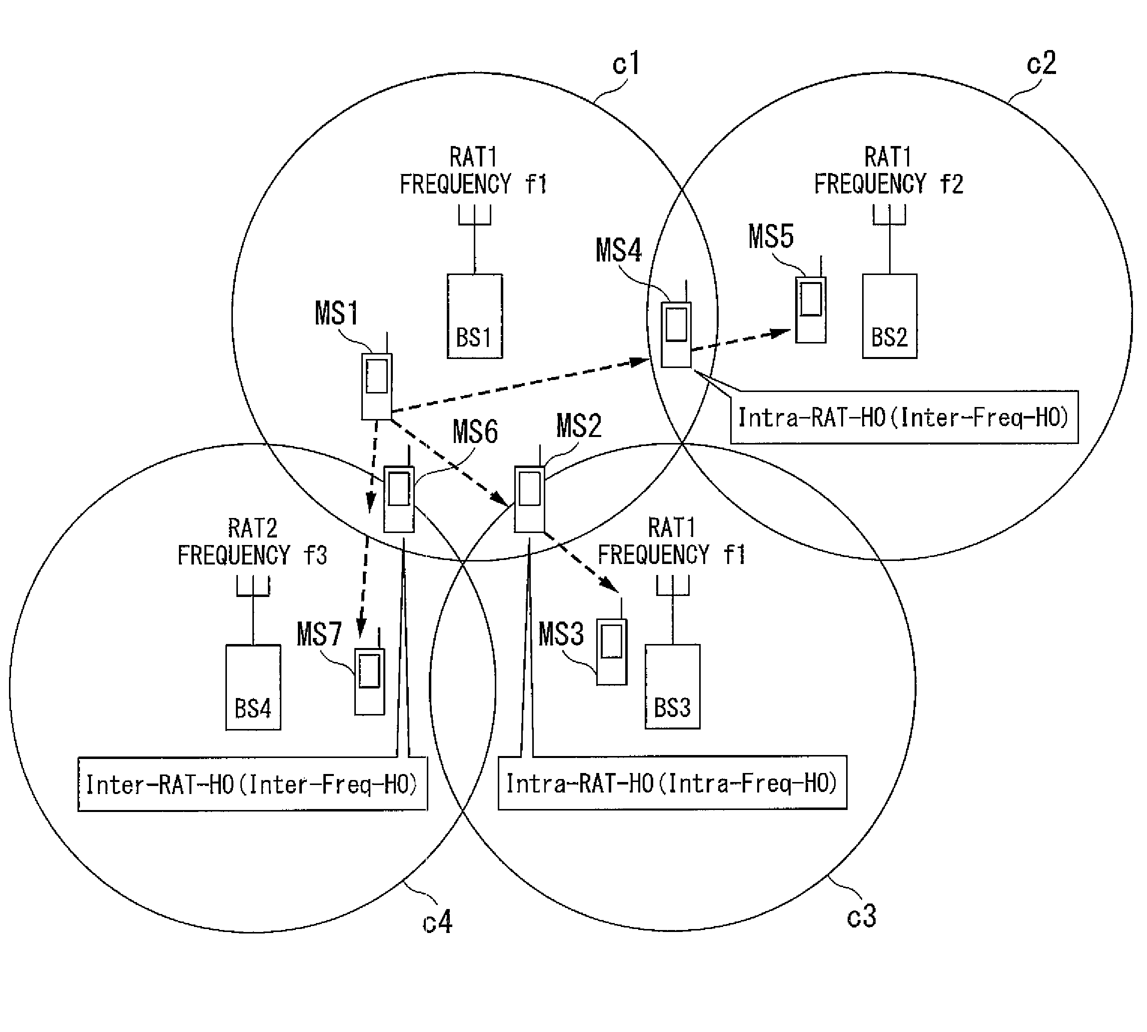
[0160]Hereinafter, a mobile communication system according to the present invention is explained. In the present embodiment, a gap generation period in the active mode is controlled for Intra-RAT-HO (and Inter-Freq-HO), Inter-RAT-HO (and Inter-Freq-HO), and Intra-RAT-HO (Intra-Freq-HO).

[0161]As explained in the first embodiment, Gap_Interval that is the parameter for controlling the gap generation period in the measurement mode is set for Intra-RAT-HO (and Inter-Freq-HO), Inter-RAT-HO (and Inter-Freq-HO), and Intra-RAT-HO (and Intra-Freq-HO) in the present embodiment.

[0162]Although a value that is longer than the gap section (e.g., Gap_1 and Gap_2) is set as Gap_Interval to enhance the packet scheduling efficiency and the power consumption of the mobile station device, the gap generation period in the measurement mode becomes longer due to the setting of Gap_Interval. In other words, the gap generation frequency becomes smaller. Due to the longer gap generation period, the periphera...


PUM


Abstract

A mobile communication system of the present invention generates a gap section based on a channel quality indication, and determines the timing or the frequency of generating the gap section based on a given parameter between the base station device and the mobile station device.

Description

TECHNICAL FIELD[0001]The present invention relates to a mobile communication system, a mobile station device, a base station device, and a mobile communication method, and more specifically, to a mobile communication system, a mobile station device, a base station device, and a mobile communication method for radio communication between cells to which the same radio frequency is allocated and which belong to cellular mobile communication systems of the same radio access technology, cells to which different radio frequencies are allocated, and cells belonging to cellular mobile communication systems of different radio access technologies (including cells to which the same radio frequency is allocated as well as cells to which different radio frequencies are allocated).[0002]Priority is claimed on Japanese Patent Application No. 2006-034513, filed Feb. 10, 2006, the content of which is incorporated herein by reference.BACKGROUND ART[0003]In the cellular mobile communication system of ...

Claims


Application Information

Patent Timeline
IPC IPC(8): H04L12/26H04J11/00H04W36/00H04W36/08H04W52/02H04W52/44H04W72/04
CPCH04L1/20H04W52/0254H04W72/12H04W28/18Y02D30/70
Inventor TSUBOI, HIDEKAZUOH, WAHOH
Owner SHARP KK
Why Eureka
Try Eureka