Timing chain drive unit

Active Publication Date: 2009-07-02
TSUBAKIMOTO CHAIN CO
View PDF8 Cites 12 Cited by
  • Summary
  • Abstract
  • Description
  • Claims
  • Application Information

AI Technical Summary

Benefits of technology

[0012]As the sprockets rotate, the pitch of the teeth on the driven sprocket at the point of disengagement, and/or the pitch of the teeth of the driving sprocket at the point of engagement, change continuously, causing a cyclic change in the length of the tension span of the chain traveling from the driven sprocket toward the driving sprocket. This changing in the length of the tension span reduces variations in tension in the chain caused by load variations imparted to the driven sprocket by the camshaft or other mechanism that it operates. In this way, load variations can be absorbed without lateral displacement of the chain and without applying a lateral force to the chain. Consequently, the overall timing chain drive unit is simplified, and can be made smaller and lighter in weight, and vibration and noise can be reduced.
[0013]When the sprocket tooth pitch increases and decreases circumferentially so that it varies cyclically at the disengagement point or at the engagement

Problems solved by technology

Accordingly, conventional timing chains are excessively heavy, the overall weight of the drive unit is high, and excessive noise is generated.
Thus, the conventional timing chain drive unit is not well adapted to demands for size reduction, weight reduction and noise reduction in internal combustion engines.
However, in the case of a

Method used


Image

  • Timing chain drive unit
  • Timing chain drive unit
  • Timing chain drive unit

Examples


Example

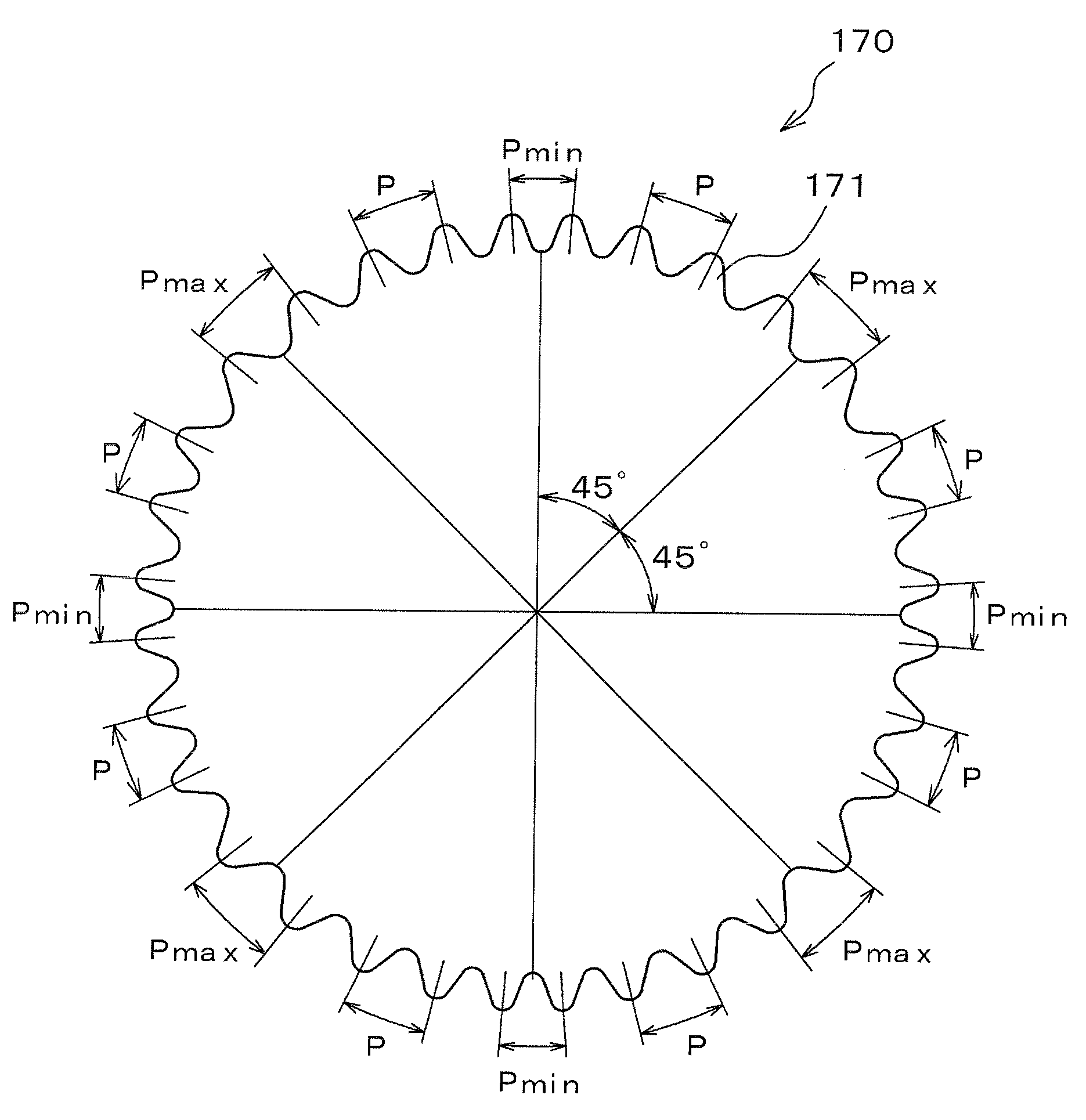
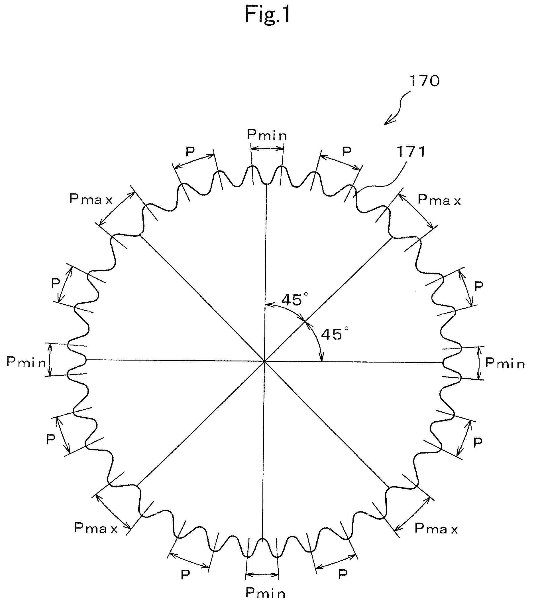
[0020]In accordance with the invention, in a timing chain drive unit, the teeth of a driving sprocket, the teeth of a driven sprocket from which the chain travels toward the driving sprocket, or the teeth on both sprockets, are arranged at unequal intervals around the circumference of the sprocket. The arrangement of teeth, which will be described below, allows cyclic load changes to be absorbed without applying a lateral force to the chain, i.e., a force in any direction other than in the direction of travel of the chain. Consequently, the timing chain drive unit can have fewer movable components so that it can be structurally simple, smaller in size, and lighter in weight, than other timing chain drive units designed to address the problem of cyclic load variations. The invention decreases vibration and noise and can be realized in various embodiments.

[0021]FIG. 1 shows a sprocket of a timing chain drive unit according to one embodiment of the invention, the drive unit being adapt...


PUM


Abstract

In a timing chain drive unit the tooth pitch of a driven sprocket from which a tension span of the chain travels toward a driving sprocket varies cyclically around the circumference of the driven sprocket and cyclically increases and decreases the length of the tension span in synchronism with load variations imparted to the driven sprocket by a valve-operating camshaft.

Description

CROSS-REFERENCE TO RELATED APPLICATION[0001]This application claims priority on the basis of Japanese patent application 2007-333955, filed Dec. 26, 2007. The disclosure of Japanese application 2007-333955 is hereby incorporated by reference.FIELD OF THE INVENTION[0002]The invention relates to a timing chain drive unit in which a predetermined drive ratio is maintained between a driving sprocket and a driven sprocket connected in driving relationship by an endless chain. The invention relates more particularly to the reduction of the influence of changes in tension in a timing chain, and to the reduction of vibration and noise in a timing drive.BACKGROUND OF THE INVENTION[0003]As shown in FIG. 5, a timing chain drive unit 500, in a dual overhead cam (DOHC) internal combustion engine, transmits power, by means of a chain CH, from a driving sprocket 550 to driven sprockets 560 and 570. A pivoted slack-side chain guide, in sliding contact with a part of the chain CH that travels from t...

Claims


Application Information

Patent Timeline
IPC IPC(8): F16H55/30
CPCF01L1/022F01L1/16F01L2001/0537F01L2810/03F01L2810/04F16H55/30F16H2055/306F01L1/02F16H7/08
Inventor NAKANO, YOSHIKAZUSAKURA, SHUNJIKUNIMATSU, KOHEI
Owner TSUBAKIMOTO CHAIN CO
Why Eureka
Try Eureka