
MRI apparatus and magnetic resonance imaging method

a technology of magnetic resonance imaging and mri apparatus, which is applied in the field of mri apparatus for imaging a blood flow, can solve problems such as narrowing the range of rendered blood flow, and achieve the effect of intelligible rendering

Inactive Publication Date: 2009-07-02
GE MEDICAL SYST GLOBAL TECH CO LLC
View PDF16 Cites 3 Cited by
  • Summary
  • Abstract
  • Description
  • Claims
  • Application Information

AI Technical Summary

Benefits of technology

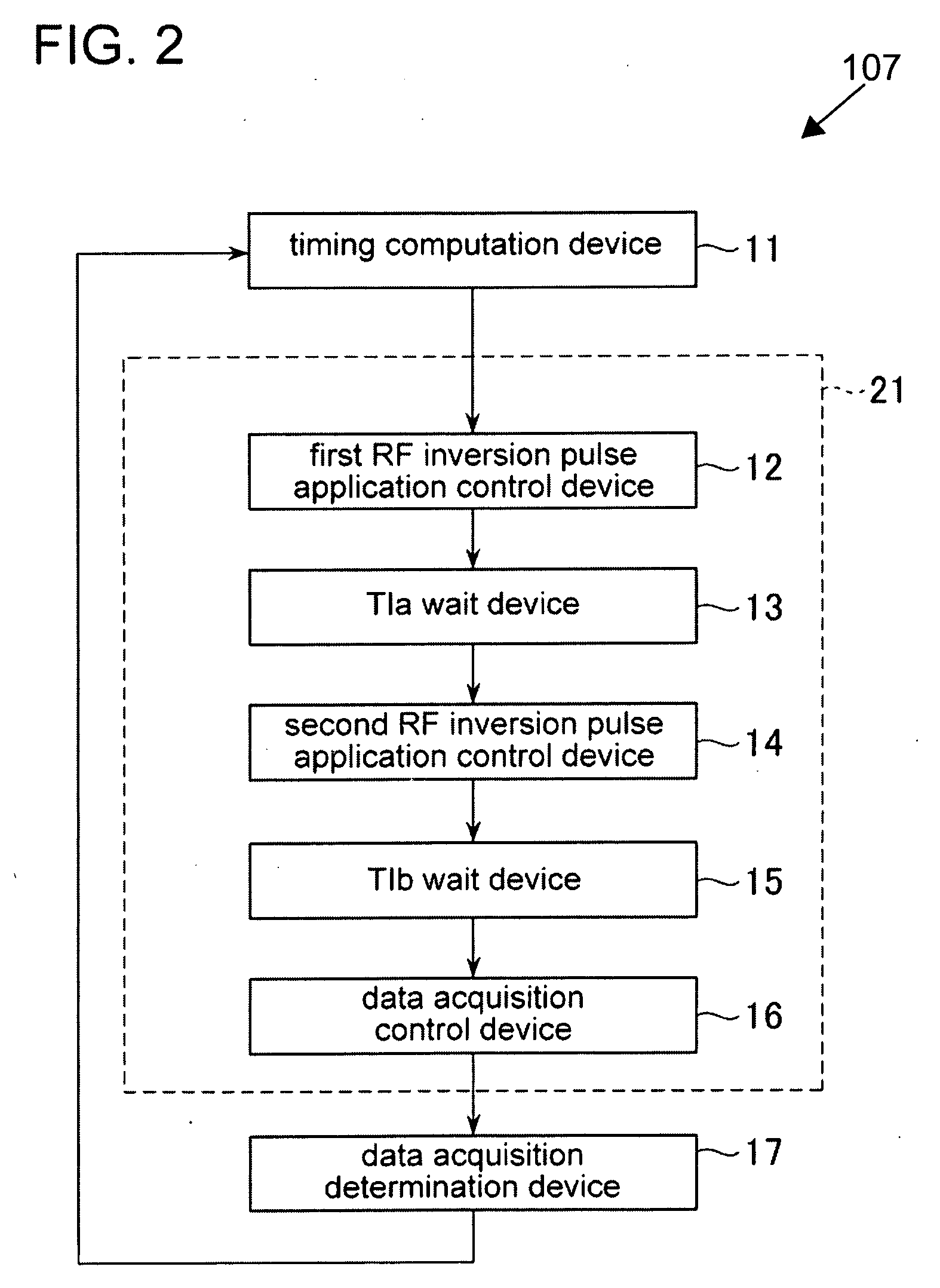
[0007]During the second inversion period, the second longitudinal magnetization inverting device inverts a longitudinal magnetization direction of the blood in process of longitudinal magnetization recovery and inverts a longitudinal magnetization direction of a tissue in the imaging region and the second region. At the end of the second inversion period, the longitudinal magnetization component Mz of the imaging region and the second region is set to −1. The longitudinal magnetization component Mz of blood in process of longitudinal magnetization recovery is in the range of −1<Mz<1. Accordingly, the blood can be more intensely rendered than the other tissues by starting a data acquisition period at a time point when the longitudinal magnetization for the tissue in the imaging region and the second region reaches or approximately reaches a null point.

Problems solved by technology

The method described above may narrow a rendered blood flow range when imaging a patient whose blood flow is slow.

Method used


Image

  • MRI apparatus and magnetic resonance imaging method
  • MRI apparatus and magnetic resonance imaging method
  • MRI apparatus and magnetic resonance imaging method

Examples


Embodiment Construction

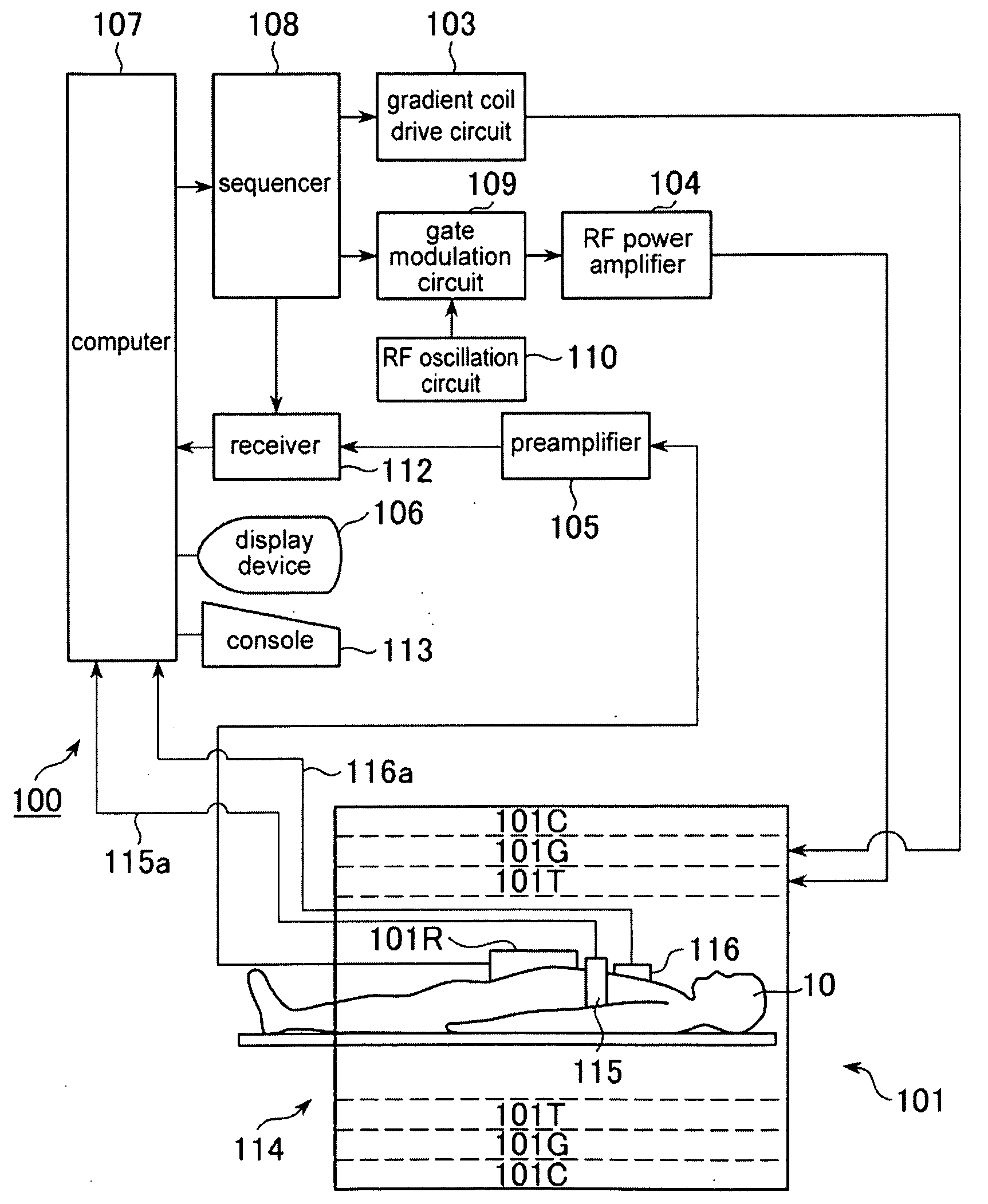
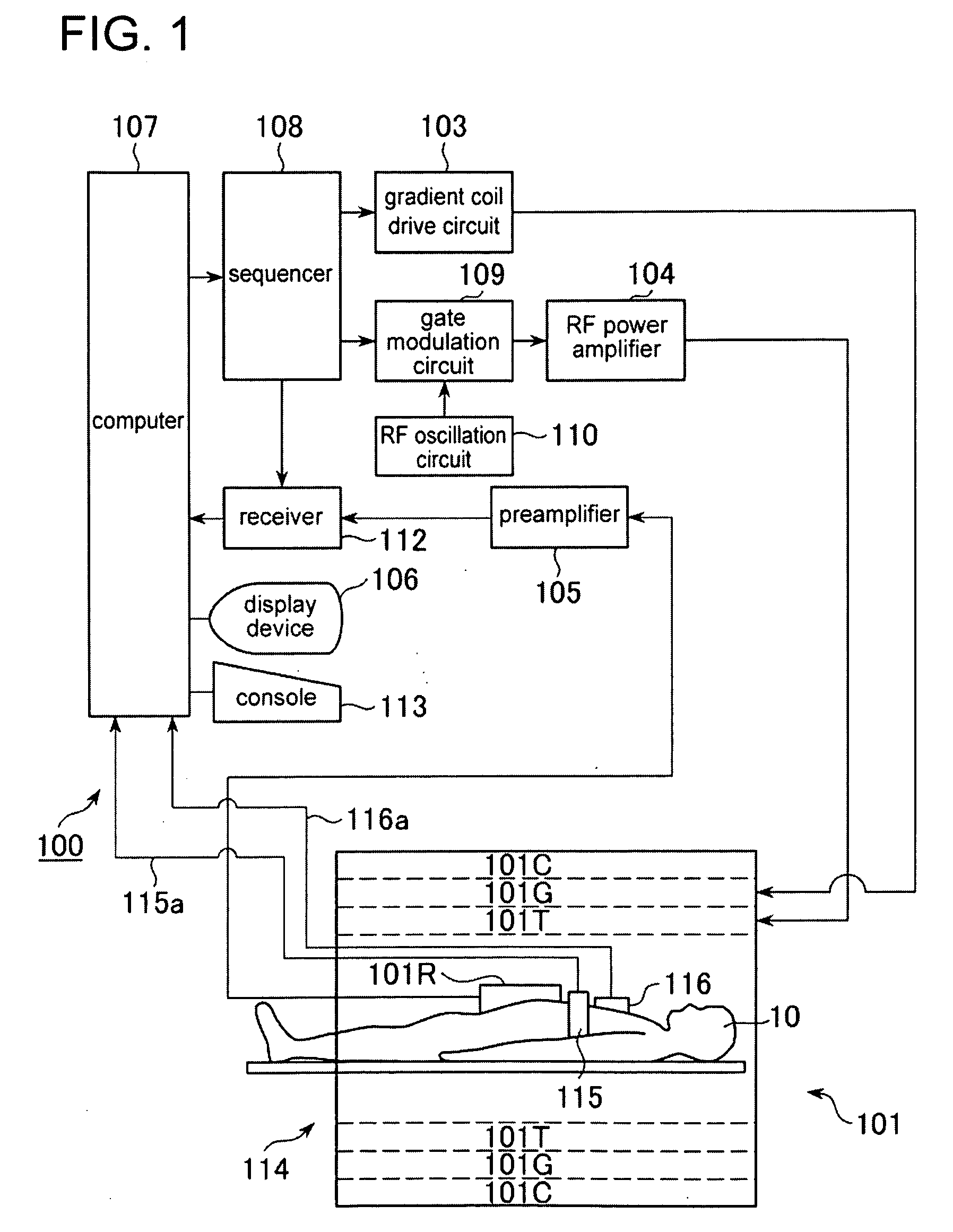
[0030]Embodiments of the present invention will be described in further detail with reference to the accompanying drawings. The invention is not limited to the embodiments described herein.

[0031]FIG. 1 is an example of a block diagram showing an exemplary MRI (Magnetic Resonance Imaging) apparatus 100.

[0032]The MRI apparatus 100 includes a magnet assembly 101. The magnet assembly 101 has a bore 114 for inserting a subject 10. The magnet assembly 101 also includes a static magnetic field coil 101C, a gradient coil 101G, and a transmission coil 101T.

[0033]The static magnetic field coil 101C forms a constant static magnetic field to the inside of the bore 114. The gradient coil 101G is connected to a gradient coil drive circuit 103 and generates gradient magnetic fields along X, Y, and Z axes. The transmission coil 101T is connected to an RF power amplifier 104 and supplies an RF pulse to the inside of the bore 114.

[0034]The MRI apparatus 100 includes a bellows 115 and a heartbeat sens...


PUM


Abstract

An MRI apparatus acquires a blood signal about blood from a subject having the blood flowing from a first region to a second region via an imaging region. The apparatus includes a first longitudinal magnetization inverting device for inverting a longitudinal magnetization direction of the blood in the first region during a first inversion period, a second longitudinal magnetization inverting device that inverts a longitudinal magnetization direction of the blood in process of longitudinal magnetization recovery and inverts a longitudinal magnetization direction of tissues in the imaging region and the second region during a second inversion period after the first inversion period, and a data acquisition device that acquires a blood signal about blood flowing from the first region to the imaging region during a data acquisition period after the second inversion period.

Description

CROSS REFERENCE TO RELATED APPLICATIONS[0001]This application claims the benefit of Japanese Patent Application No. 2007-340864 filed Dec. 28, 2007, which is hereby incorporated by reference in its entirety.BACKGROUND OF THE INVENTION[0002]The embodiments described herein relate to an MRI apparatus for imaging a blood flow and a magnetic resonance imaging method for a blood flow.[0003]Conventionally, an MRI apparatus is used to image a blood flow in a blood vessel. For example, the Time-SLIP technique is known as a method of imaging a blood flow (see Image Information Medical, September 2006, pp. 952-957).[0004]The method described above may narrow a rendered blood flow range when imaging a patient whose blood flow is slow.[0005]It is desirable that the problem described previously is solved.BRIEF DESCRIPTION OF THE INVENTION[0006]An MRI apparatus acquires a blood signal about blood from a subject having the blood flowing from a first region to a second region via an imaging region ...

Claims


Application Information

Patent Timeline
Patent Type & Authority Applications(United States)
IPC IPC(8): A61B5/055
CPCA61B5/0263A61B5/055G01R33/5635G01R33/5601G01R33/56308A61B5/7285
Inventor TAKEI, NAOYUKI
Owner GE MEDICAL SYST GLOBAL TECH CO LLC
Learn More