

Burner and gas turbine combustor
a gas turbine and combustor technology, applied in the field of burners, gas turbine combustor and combustor retrofit, can solve problems such as nox emissions, and achieve the effect of reducing nox emissions and high flame stability
- Summary
- Abstract
- Description
- Claims
- Application Information
AI Technical Summary
Benefits of technology
Problems solved by technology
Method used
Image

Examples
first embodiment
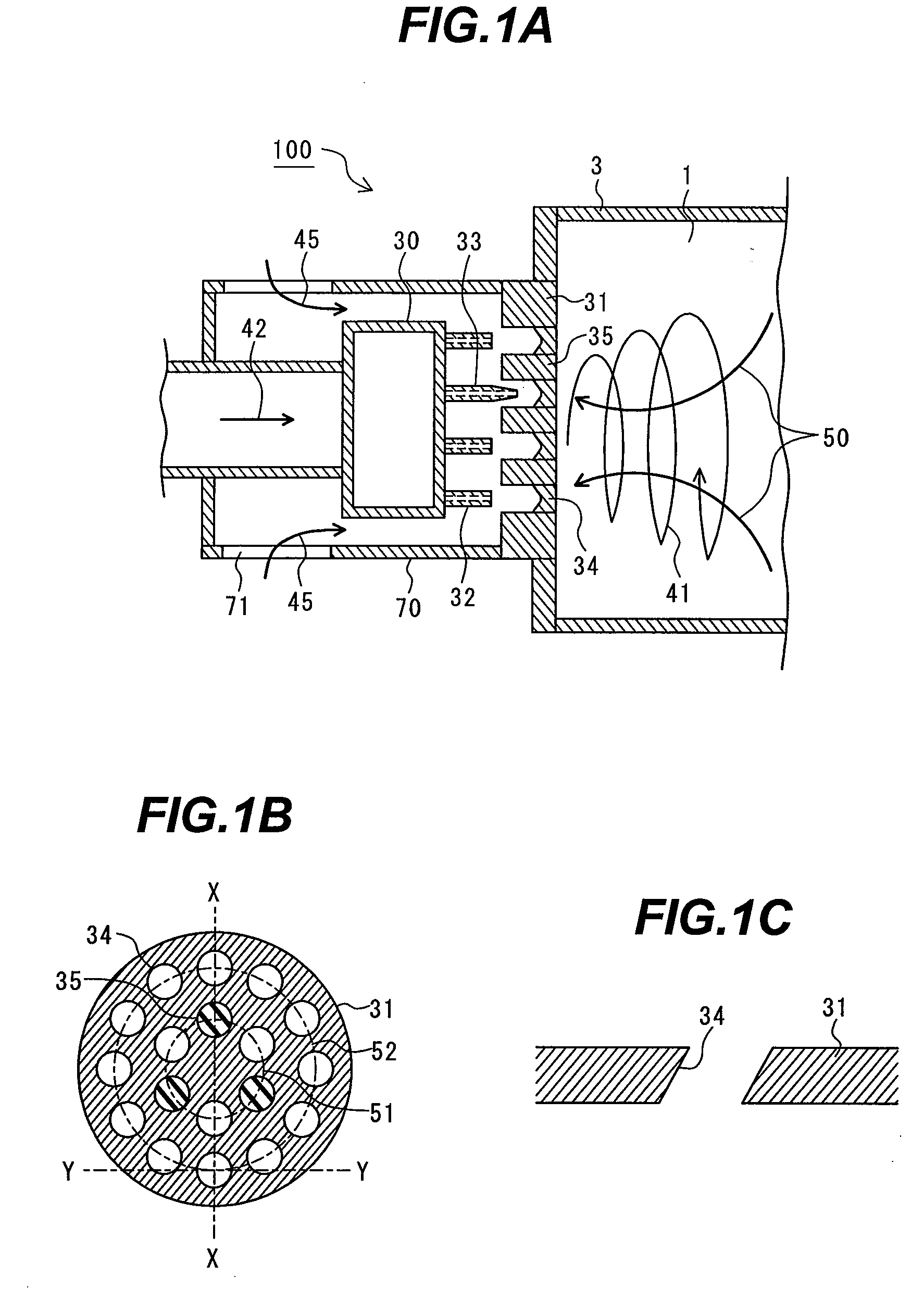
[0039]FIG. 1A is a lateral cross-sectional view of a burner according to a first embodiment, taken along line X-X of FIG. 1B. FIG. 1B is a front view of an air hole member 3 as viewed from a chamber 1. FIG. 1C is a cross-sectional view taken along line Y-Y of FIG. 1B. In the embodiment, each of all air holes has a central axis inclined with respect to a burner central axis. Specifically, as shown in FIG. 1C, the path central axis of each air hole is inclined in the circumferential direction of the air hole member 31. For this reason, when the air hole member 31 is cut in X-X section, the inclination of the air hole is apparently depicted as in FIG. 1A.
[0040]The burner 100 of the embodiment includes a fuel header 30 adapted to distribute fuel to a plurality of fuel nozzles 32, 33 on the downstream side thereof; the fuel nozzles 32, 33 joined to the fuel header 30 to jet out fuel into the plurality of air holes; and the air hole member 31 provided with the air holes 34, 35. The air ho...
second embodiment
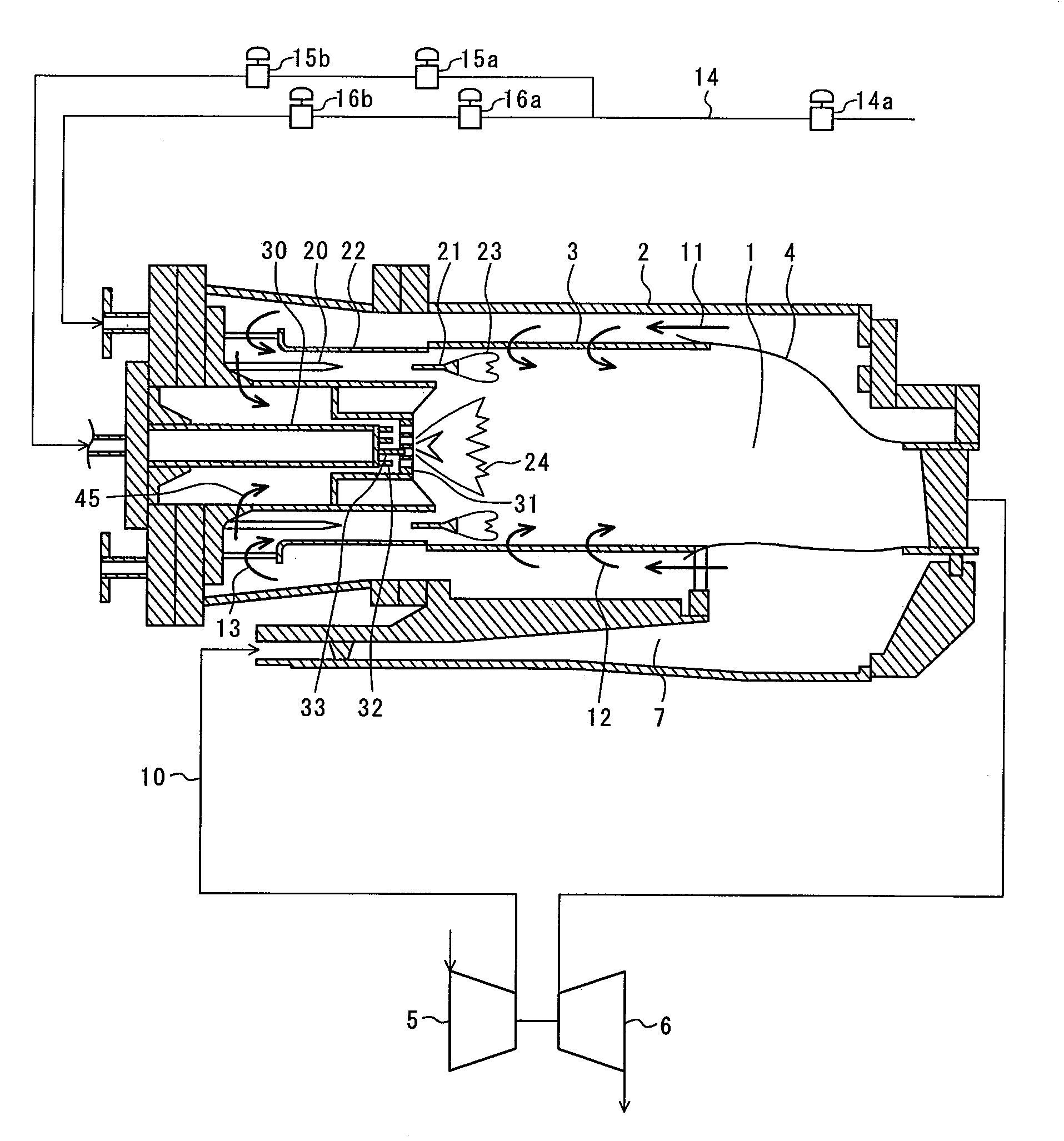
[0060]A second embodiment is described in which the burner structure of the invention is applied to a pilot burner of a combustor. In the embodiment, a premix gas turbine combustor is described as one example of the combustor. FIG. 5 schematically illustrates the whole of a gas turbine. FIG. 6 is a front view of a burner.
[0061]Compressed air 10 delivered from a compressor 5 flows in a combustor through a diffuser 7 and passes through between an external cylinder 2 and a combustor liner 3. A portion of the compressed air 11 flows into a chamber 1 as cooling air for the combustor liner 3. The remainder of the compressed air 11 passes through a premix passage 22 and an air hole member 31 as combustion air 13 and 45, respectively, and flows into the chamber 1. Fuel and the air are mixed and burned inside the combustor 1 to create combustion gas. The combustion gas is discharged from the combustor liner 3 and supplied to a turbine 6.
[0062]In the embodiment, a fuel supply system 14 with a...
third embodiment
[0070]In recent years, gas turbines have been required to have the broad versatility of fuel because of the issue of depleted energy resources. Fuel having a high hydrogen content increases burning velocity, whereas fuel having a high nitrogen content lowers flame temperature to decrease burning velocity. Thus, fuel characteristics largely vary depending on the fuel compositions. This needs to tune the arrangement and number of air holes in accordance with the fuel composition. In addition, NOx emissions, an operating range, etc. required vary depending on gas turbine-use regions. It is also necessary to flexibly deal with them. To meet the necessity, the arrangement variations of the pairs of the fuel nozzles 32 and air holes 34 and the pairs of the fuel nozzles 33 and the air holes 35 in the first embodiment are changed to enable the control of the NOx emissions and of flame stability.
[0071]FIG. 8 is a front view of a burner according to a third embodiment. In the present embodime...
PUM
 Abstract
Description
Claims
Application Information