

Electromagnetic Lock Monitoring System
a technology of electronic lock and monitoring system, applied in the field of electronic lock, can solve the problems of only monitoring half of the actual magnetic field available, and the magnetic field directly adjacent to the hall effect device is actually monitored
- Summary
- Abstract
- Description
- Claims
- Application Information
AI Technical Summary
Benefits of technology
Problems solved by technology
Method used
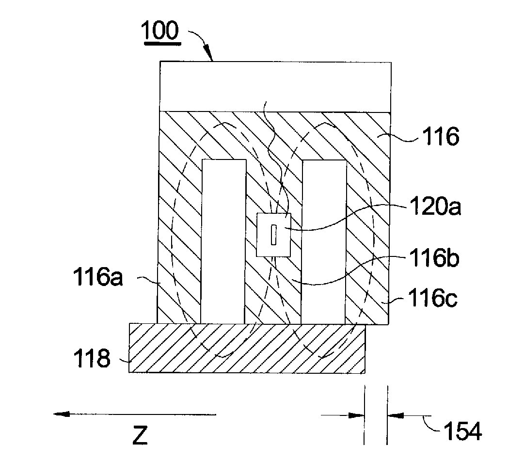
Image

Examples
Embodiment Construction
[0020]Referring to FIG. 1, the Hall effect comes about due to the nature of the current in a conductor. Current I consists of the movement of many small charge-carrying “particles” (typically, but not necessarily, electrons). Moving charges experience a force, called the Lorentz Force, when a magnetic field B is present that is not parallel to their motion. When such a magnetic field is absent, the charges follow an approximately straight ‘line of sight’ path 10. However, when a perpendicular magnetic field B is applied, their path is curved 12 so that moving charges accumulate on one face 14 of the material. This leaves equal and opposite charges exposed on the other face 16, where there is a scarcity of mobile charges. The result is an asymmetric distribution of charge density across the Hall element 18 that is perpendicular to both the ‘line of sight’ path 10 and the applied magnetic field B. The separation of charge defines an electric field that opposes the migration of further...
PUM
 Abstract
Description
Claims
Application Information