Shell for drum and drum using the same

Active Publication Date: 2009-07-09
YAMAHA CORP
View PDF4 Cites 4 Cited by
  • Summary
  • Abstract
  • Description
  • Claims
  • Application Information

AI Technical Summary

Benefits of technology

[0019]In the invention, the plurality of single-panels are jointed in decreasing order of density from a center portion in the thick direction of the laminated plywood-panel toward an outermost portion and an innermost portion, such that a single-panel having the highest density is at the center portion, and single-panels having the lowest densities are arranged at the outermost portion and the innermost portion. That is, the high-specific-gravity (high-rigidity) single-panel is arranged at the center portion, and low-sp

Problems solved by technology

However, in a shell formed by enclosing a single-panel having low specific gravity between plywood-panels having high specific gravity, since the outer side of the single-panel having low specific gravity is pressed by the single-panel having high specific gravity, there is considerable loss of vibrational energy due to internal abrasion.
This leads to problems that the vibration of drum is rapidl

Method used


Image

  • Shell for drum and drum using the same
  • Shell for drum and drum using the same
  • Shell for drum and drum using the same

Examples


Example

[0025]An embodiment of the present invention will be explained in detail with reference to the drawings.

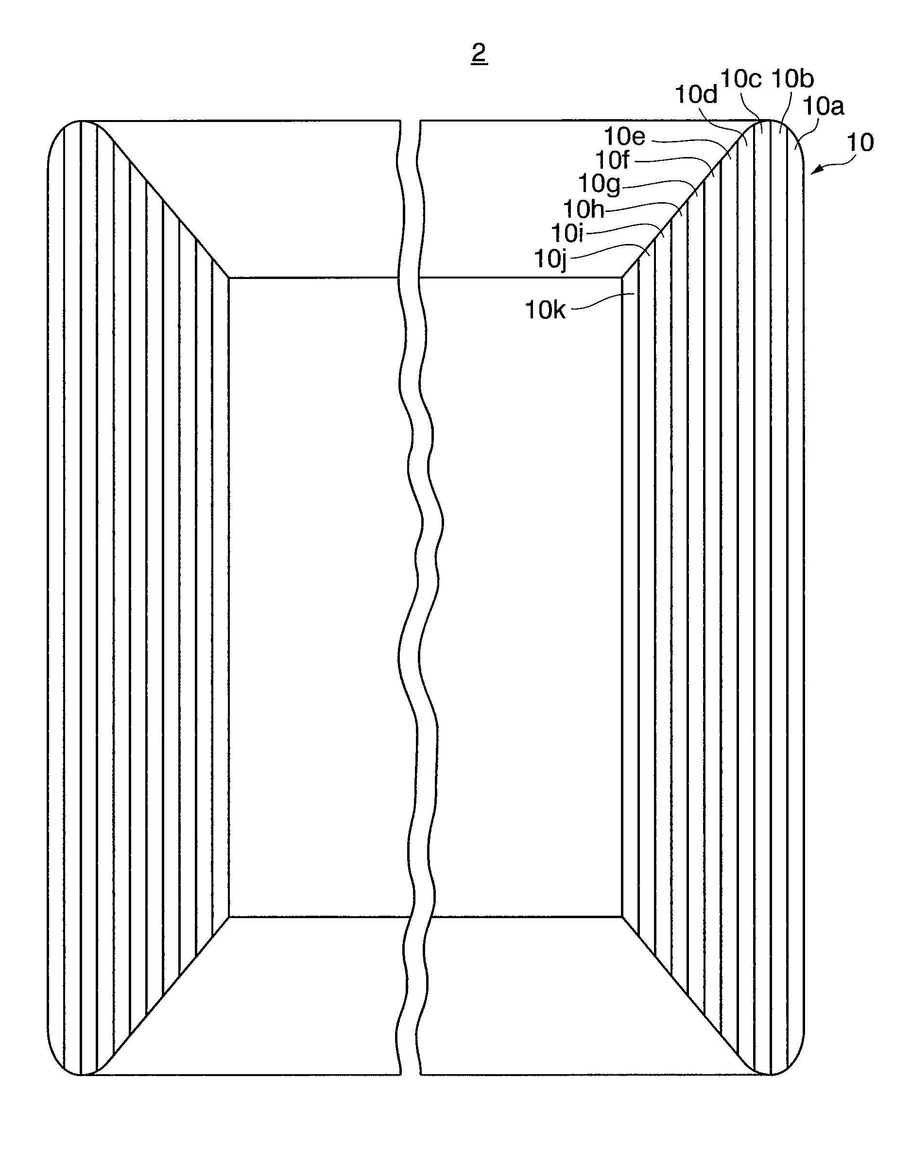
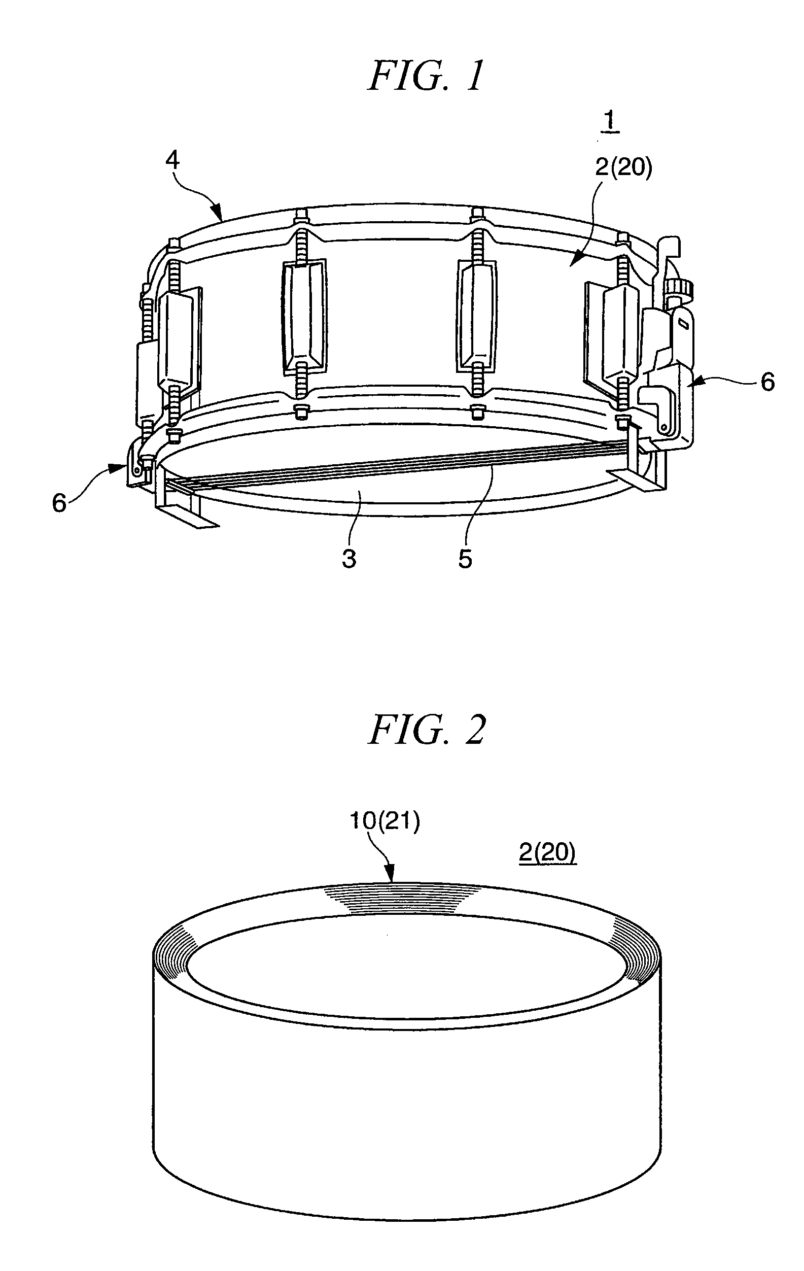
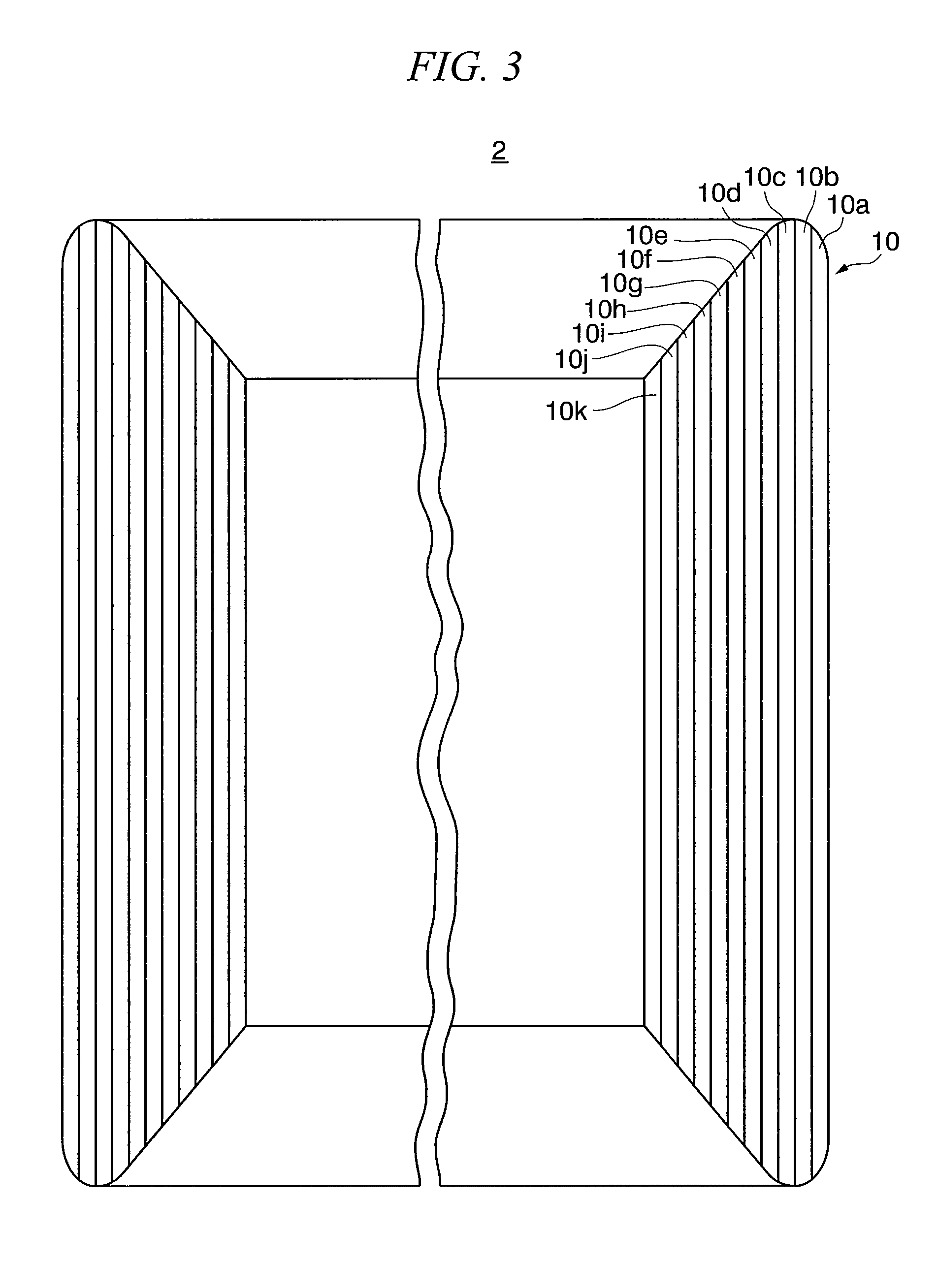
[0026]FIG. 1 is an external perspective view showing a snare drum according to an embodiment of the invention. FIG. 2 is an external perspective view showing a shell of the snare drum shown in FIG. 1. FIG. 3 is a cross-sectional view showing the shell of the snare drum shown in FIG. 1. FIG. 4 is an exploded perspective view showing a plywood-panel constituting the shell of the snare drum shown in FIG. 1. As shown in FIGS. 1 to 4, a snare drum 1 includes a shell 2, two drum heads 3, head-supporting tensile parts 4, a drum snare 5, a Backen mechanism 6, and so on. The shell 2 is formed in the shape of a cylinder with both ends open. The two drum heads 3 are provided such that they cover the two open ends of the shell 2 in a tensioned state. The head-supporting tensile parts 4 support the drum heads 3 in a tensioned state. The drum snare 5 is provided in a tensioned state over the dr...


PUM


Abstract

A shell for drum according to the present invention includes a laminated plywood-panel including a plurality of single-panels having different densities, the plurality of single-panels being jointed in decreasing order of density from a center portion in a thick direction of the laminated plywood-panel toward an outermost portion and an innermost portion, such that a single-panel having a highest density is arranged at the center portion, and single-panels having lowest densities are arranged at the outermost portion and the innermost portion.

Description

BACKGROUND OF THE INVENTION[0001]1. Field of the Invention[0002]The present invention relates to a shell for drum such as a bass drum, a snare drum, and a marching drum, and a drum using the same.[0003]Priority is claimed on Japanese Patent Application No. 2008-002220, filed Jan. 9, 2008, the content of which is incorporated herein by reference.[0004]2. Description of Related Art[0005]A shell which a drum head of a drum is provided over in a tensioned state is normally made from various materials such as wood, metal such as aluminum alloy, and fiber reinforced plastic (FRP) (see for example Japanese Unexamined Patent Application, First Publication No. H11-45087, Japanese Patent Publication No. 332477 {Japanese Unexamined Patent Application, First Publication No. 2001-67066}, and Japanese Examined Utility Model Application, Second Publication No. S53-47939). Most shells are made from wood, since this obtains a musically warm sound.[0006]A wood of appropriate hardness and superior aco...

Claims


Application Information

Patent Timeline
IPC IPC(8): G10D13/02B27N5/00
CPCG10D13/028G10D13/22
Inventor ABE, BANRIABE, TAKUYA
Owner YAMAHA CORP
Why Eureka
Try Eureka