Bubble lift system and bubble lift method

Active Publication Date: 2014-06-19
MODEC
View PDF33 Cites 7 Cited by
  • Summary
  • Abstract
  • Description
  • Claims
  • Application Information

AI Technical Summary

Benefits of technology

[0044]According to the bubble lift system and the bubble lift method of the present invention, a pressurized chamber is provided at an upper end portion of a riser pipe, whereby in bubble lift in a deep water region at a water depth of 5,000 m, for example, an increase in the volume ratio occupied by bubbles at the upper end portion of the riser pipe can be controlled within several ten times, which is a practical level. In contrast, in the conventional technique, the bubble lift under the same conditions is substantially impossible, because only a fluid slightly heavier by several percentages than seawater can be lifted in reality since the volume of bubbles at the upper end portion of the riser pipe becomes as much as 500 times the volume at the lower end portion of the riser pipe.
[0045]In this way, the bubble lift system can lift a to-be-lifted substance even in a deep water region which is tremendously deeper than in the case of the conventional technique, and thus can lift a target substance having a higher specific gravity. In addition, there is produced an effect of enabling efficient lifting by reducing a pressure loss that is substantially proportional to a square of the flow velocity. For example, the bubble lift of a fluid having more than two times the specific gravity of seawater at a water depth of 5,000 m is made possible with practically sufficient performance.
[0046]Moreover, by providing deaerators to middle portions of the riser pipe, not only the upper end portion of the riser pipe but also several locations in a shallow water region can be set as locations where the bubble ratio reaches the maximum. Thus, the volume ratio occupied by bubbles can be made uniform in the whole riser pipe from the deep water region to the shallow water region. As a result, the bubble r

Problems solved by technology

In this case, an upward flow cannot be generated inside the riser pipe, and consequently the pushing force due to a pressure difference between the inside and the outside cannot be generated at the lower end portion of the riser pipe.
As a result, as the fluid mixture approaches the upper end portion of the riser pipe, there arise problems, for example, that the flow velocity of the upward flow becomes excessively high; and a volume ratio of a to-be-lifted substance to the fluid mixture decreases relative to the rest of the mixture, which accordingly lowers the lifting efficiency, or in the worst case, make it impossible to lift

Method used


Image

  • Bubble lift system and bubble lift method
  • Bubble lift system and bubble lift method
  • Bubble lift system and bubble lift method

Examples


Example

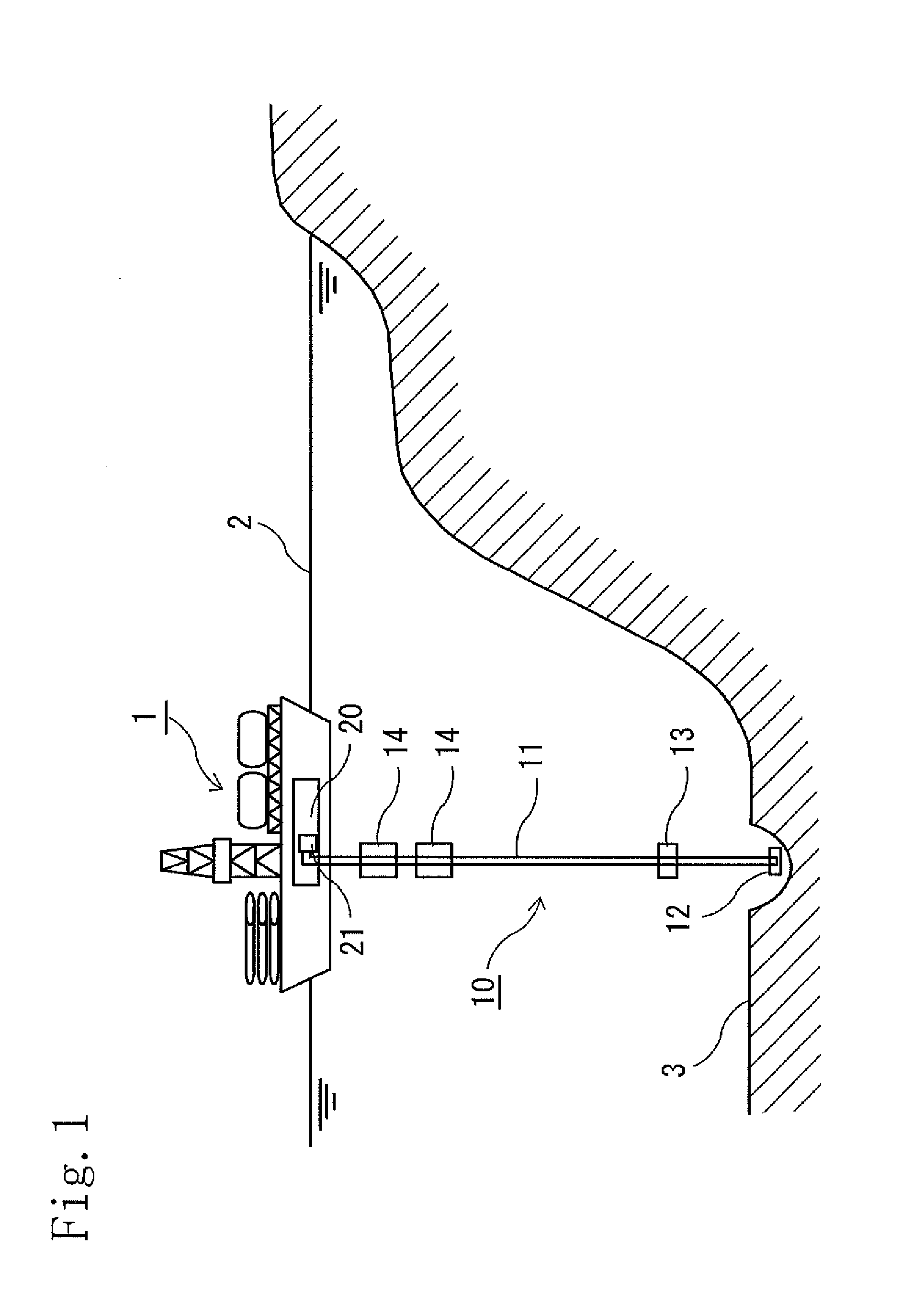
[0058]Hereinafter, description is provided for a bubble lift system and a bubble lift method of embodiments according to the present invention. In this description, the present invention is explained by using an example of lifting a resource on a sea bottom by using a drill ship in the ocean, but the application range of the present invention is not limited to the ocean, but also includes lake, river, and the like.

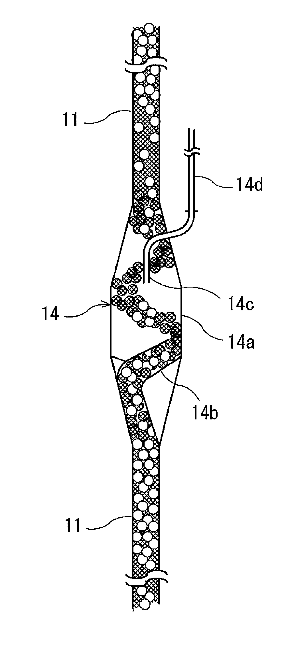
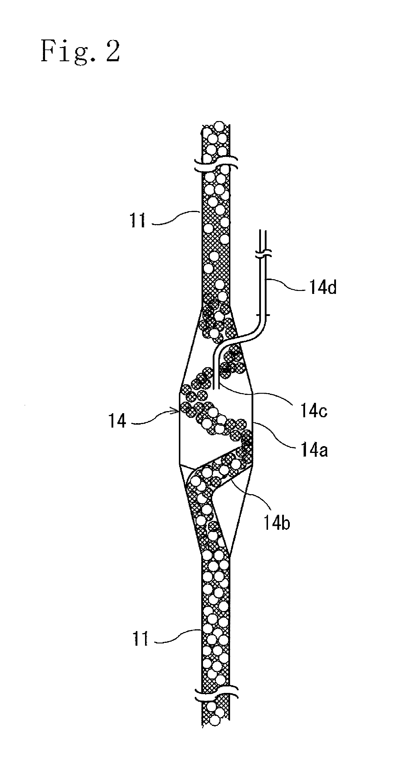
[0059]A bubble lift system 10 of an embodiment according to the present invention has a configuration illustrated in FIG. 1. The bubble lift system 10 is a system used in a drill ship (drilling-rig vessel) 1 floating on a sea surface (water surface) 2 to lift a resource existing on a sea bottom (water bottom) 3 or under the sea bottom 3. The bubble lift system 10 includes a riser pipe 11, a collector 12, a gas injection apparatus 13, a deaerator 14, and a receiving apparatus 20.

[0060]This bubble lift system 10 is a system configured to lift a solid substance or a liquid su...


PUM

PropertyMeasurementUnit
Pressureaaaaaaaaaa
Specific gravityaaaaaaaaaa
Velocityaaaaaaaaaa

Abstract

In a bubble lift system 10, a pressurized chamber 21 is provided at an upper end portion of a riser pipe 11, and applies a pressure to an upper portion inside the riser pipe 11 to suppress an increase in the volume ratio of bubbles to a fluid mixture rising inside the riser pipe 11 in a shallow water region. In this configuration, the upper end of the riser pipe 11 is not opened to the atmosphere but is inserted into the pressurized chamber 21 under a high pressure to thereby prevent expansion of the bubbles and gas. In addition, a deaerator 14 for discharging bubbles separated by a centrifugal force is also provided in a middle portion of the riser pipe 11 in a shallow water region to thereby make the bubbles distributed more evenly inside the whole riser pipe 11. Thus, provided are the bubble lift system 10 and a bubble lift method that are efficient and employable even in a deep water region.

Description

TECHNICAL FIELD[0001]The present invention relates to a bubble lift system and a bubble lift method for lifting a solid substance or a liquid substance such as sand, sediments, or minerals on a deep water bottom such as a sea bottom, a lake bottom or a river bottom, or in the ground further below the water bottom to a place above the water surface.BACKGROUND ART[0002]The gas lift technique has been widely used in crude oil production in order to efficiently lift a heavy oil, which is slightly lighter in weight than seawater, from a submarine oil field having a low natural flow pressure. In this technique, a gas having a small and relatively negligible mass is injected into a liquid inside a riser pipe to reduce the pressure of a liquid column inside the pipe by an amount corresponding to the volume ratio of the gas, and thereby a pushing force by a pressure of the seawater outside the riser pipe or a reservoir pressure is generated at the lower end portion of the riser pipe. It is c...

Claims


Application Information

Patent Timeline
IPC IPC(8): F04F1/20
CPCE02F3/8833E21C50/00B01D19/0057E02F3/9243F04F1/20F04F1/18
Inventor NAKAMURA, TAKUJUKAWASE, MASAKI
Owner MODEC
Why Eureka
Try Eureka