
Pneumatic tire and method for manufacturing the same

a pneumatic tire and pneumatic technology, applied in the field of pneumatic tires, can solve the problems of radio noise, radio noise, and inability to satisfy the request that the conductive layer be exposed in the center portion or the mediate portion, and achieve the effect of preventing from being sheathed

Active Publication Date: 2009-07-09
TOYO TIRE & RUBBER CO LTD
View PDF11 Cites 33 Cited by
  • Summary
  • Abstract
  • Description
  • Claims
  • Application Information

AI Technical Summary

Benefits of technology

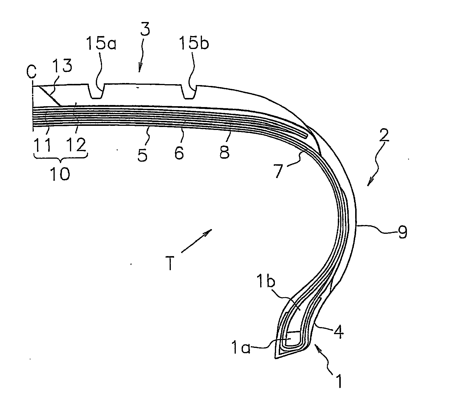
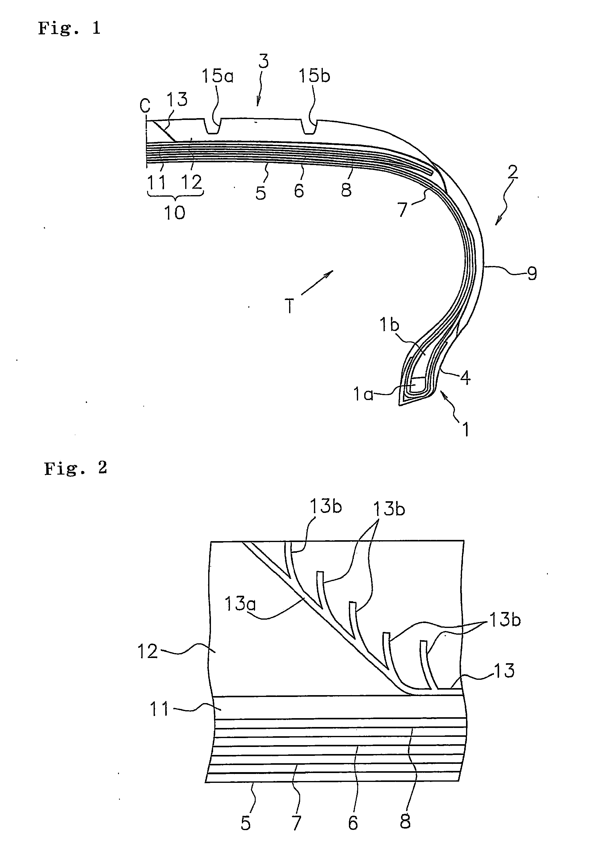
[0011]The pneumatic tire according to the invention can release the static charge generated on a vehicle body and / or the tire to the road surface through the conductive layer extending from the tread surface to the bottom surface or side face of the non-conductive rubber layer. Also, since the conductive layer has the main portion and the branch portions as described above, the conductive layer can be exposed to the tread surface at plural points, thereby the end portion of the conductive layer can be prevented from being sheathed while curing processing of the tire. As a result, the releasing function of the static charge can be reliably obtained from initial stage of wear irrespective of exposed portion of the conductive layer.
[0018]In the method for manufacturing a pneumatic tire, it is preferred that the second rubber part covers a inner periphery side face of the first rubber part, and in the conductive layer forming process, the rubber ribbon is wound being inclined with respect to a diameter direction of the tire toward an inner periphery of the tire. With this arrangement, the conductive layer having the main portion and the branch portions as described above can be formed easily. The face at the inner periphery side of the first rubber part means here the face that comes to the inner periphery side when the rubber ribbon is wound along the circumferential direction of the tire.

Problems solved by technology

As a result, problems like radio noises tend to occur.
When such tire is practically used as it is, in an initial stage of wear, the releasing function of the static charge may fail causing a problem such as radio noises.
In this case, such a request that the conductive layer be exposed in the center portion or mediate portion is not satisfied.
Even when the conductive layer is exposed in a groove, the problem cannot be solved.
Since selection of exposing location of the conductive layer depends on a pattern design somewhat, and in view of ensuring the flexibility of the pattern design, it is not desirable that the exposing location of the conductive layer is limited to a specific location.

Method used


Image

  • Pneumatic tire and method for manufacturing the same
  • Pneumatic tire and method for manufacturing the same
  • Pneumatic tire and method for manufacturing the same

Examples


Embodiment Construction

[0026]Embodiments of the invention will be described below with reference to the accompanying drawings.

Structure of Pneumatic Tire

[0027]FIG. 1 is a cross sectional view of a pneumatic tire according to the invention taken along a tire meridian thereof. A pneumatic tire T includes a pair of bead portions 1, a pair of sidewall portions 2 each extending toward the respective outer peripheries of the tire from the bead portion 1, and a tread portion 3 continuous to the respective outer peripheries of the tire located in the sidewall portion 2. The bead portion 1 includes an annular bead la composed of a bundle of steel wires or the like sheathed with rubber and a bead filler 1b of hard rubber disposed therein.

[0028]A carcass layer 7 is composed of at least a sheet of (in this embodiment, two sheets) carcass ply laid being bridged between the bead portions 1. The carcass ply is composed of cords sheathed with rubber extending at an angle of substantially 90° with respect to the tire equa...


PUM

PropertyMeasurementUnit
angleaaaaaaaaaa
angleaaaaaaaaaa
volume resistivityaaaaaaaaaa

Abstract

A pneumatic tire according to the invention includes a cap rubber 12 as a non-conductive rubber layer and a conductive layer 13 that extends from the tread surface to the bottom surface of the cap rubber 12 through the cap rubber 12. The conductive layer 13 has a main portion 13a extending from the tread surface toward the inner periphery of the tire, and plural branch portions 13b branched from the main portion 13a and extending toward the outer periphery of the tire. At least, one of the branch portions 13b is exposed to the tread surface.

Description

BACKGROUND OF THE INVENTION[0001]1. Field of the Invention[0002]The invention relates to a pneumatic tire in which at least an outer periphery portion of the tire in a tread portion is formed of a non-conductive rubber layer, and a method for manufacturing a pneumatic tire.[0003]2. Description of the Related Art[0004]Recently, there have been proposed a pneumatic tire including a tread rubber blended with silica at a high ratio in order to reduce the rolling resistance that largely affects the fuel consumption of a vehicle and / or to increase braking performance (wet braking performance) on a wet road surface. However, compared to a tread rubber blended with carbon black at a high ratio, the electric resistance of such tread rubber is high, and accordingly, static charge generated on a vehicle body or the tire is prevented from being released to the road surface. As a result, problems like radio noises tend to occur.[0005]There has been developed a pneumatic tire provided with a solu...

Claims


Application Information

Patent Timeline
Patent Type & Authority Applications(United States)
IPC IPC(8): B60C19/00B60C1/00B29D30/08
CPCB29D30/60B60C19/08B29D2030/526Y10S152/02
Inventor KAWAKAMI, KAZUKI
Owner TOYO TIRE & RUBBER CO LTD
Learn More