Pivotable screen assembly for screened enclosures

a technology of movable screens and enclosures, which is applied in the direction of screens, insect protection, construction, etc., can solve the problems of prone to severe weather, inability to pass through the screening material quickly enough, and complete destruction of the enclosure, etc., and achieves rapid construction and installation, simple design, and low cost.

Inactive Publication Date: 2009-07-09
ELFERS JAMES
View PDF12 Cites 4 Cited by
  • Summary
  • Abstract
  • Description
  • Claims
  • Application Information

AI Technical Summary

Benefits of technology

[0013]Yet another object of the subject invention is to provide a pivotable screen assembly having gap sealing means for preventing the passage of insects and flying debris through the gap between the screen assembly and surrounding framing members.
[0014]Still another object of the s

Problems solved by technology

Unfortunately, those same warm climates which are ideal for screened enclosures are also prone to severe weather in the form of high winds and/or hurricanes.
When conventionally constructed screened enclosures of the prior art are subjected to extreme wind forces, air is unable to pass through the screening material quickly enough despite its porosity.
Because the framing surrounding the screening material is fixed and rigid the screening material can be caused to stretch and/or tear, or worse yet, the force exerted on the screens can be transferred to the surrounding framing which eventually buckles causing in some instances complete destruction of th

Method used


Image

  • Pivotable screen assembly for screened enclosures
  • Pivotable screen assembly for screened enclosures
  • Pivotable screen assembly for screened enclosures

Examples


Embodiment Construction

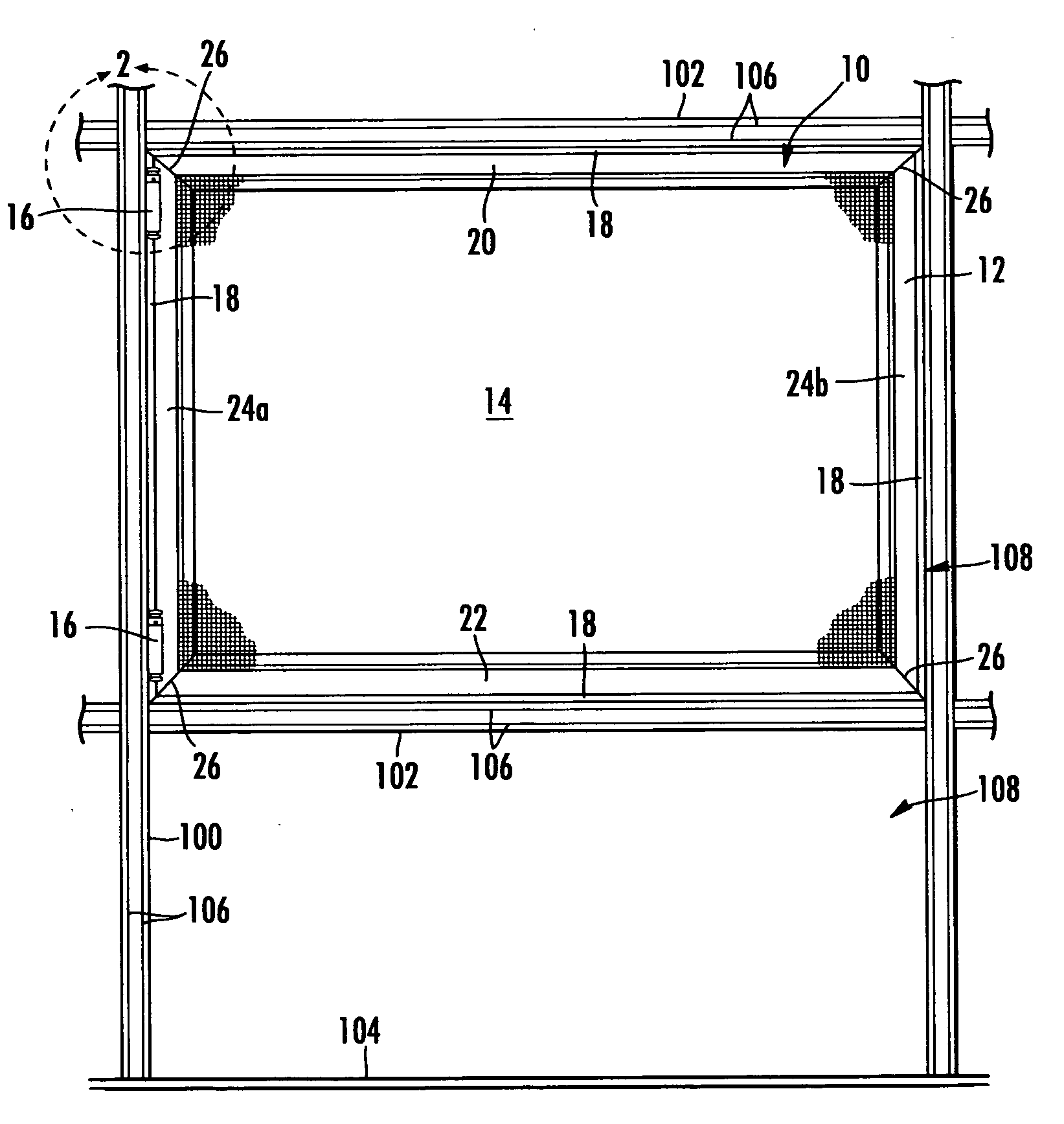
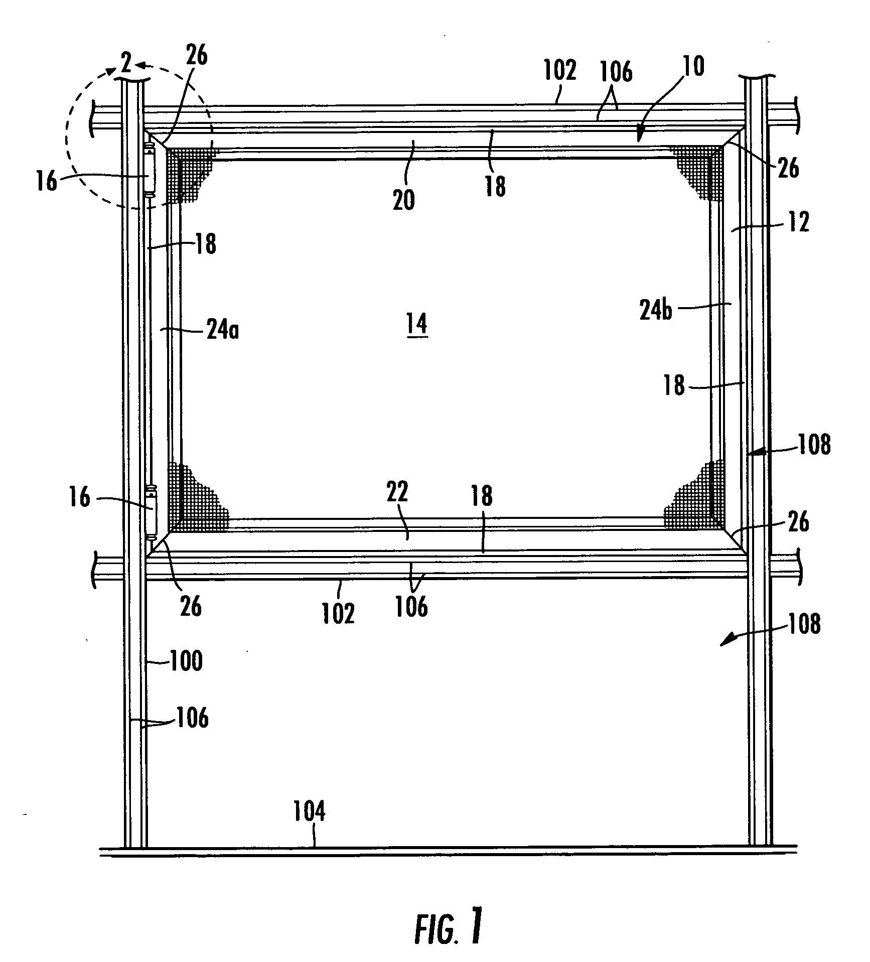
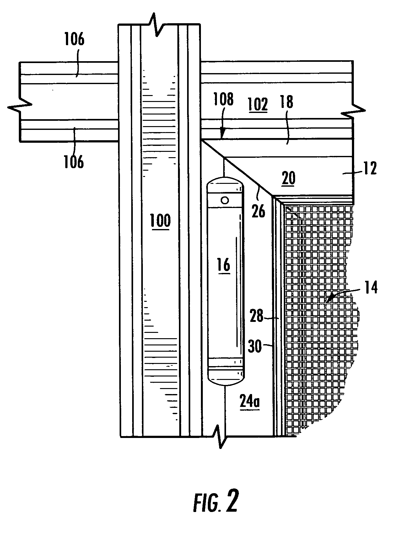
[0021]In order that the construction and benefits of the subject invention may be fully appreciated it is first necessary to understand the environment within which it is installed, namely a framed enclosure. Accordingly, reference is first made to FIGS. 1 and 2 in which there is illustrated a typical configuration of framing members which are most commonly of the extruded aluminum type. More specifically, the various framing members used to create a “pool cage” or other similar screened enclosure include: 1) vertically oriented posts 100 (sometimes called “columns”) which are the primary support means for side walls, 2) diagonally oriented beams (not shown) which are the primary support means for the roof structure, 3) horizontally oriented purlins 102 disposed between posts and between beams to impart stability and lateral support, and 4) base members 104 which are used to anchor screening material to the floor about the enclosure's perimeter. In screened enclosures of the prior a...


PUM


Abstract

A wind screen insert for framing members of screened enclosures such as pool cages and the like, the wind screen being adapted to pivot about a vertical or horizontal framing member to which it is hingedly attached. The wind screens which may be of various dimension are mounted within an opening defined by conventional posts/columns, purlins, beams, base and eve rails using at least one double acting spring hinge. The hinge allows the wind screen to pivot up to 90 degrees in either direction relative to its closed or “resting” position when a predetermined amount of force is applied to the wind screen. The hinge also automatically returns the wind screen to its original closed position when the force is diminished below the predetermined amount. The spring tension within the hinges is adjustable to permit screen movement at a desired amount of force applied to the wind screen which will be a function of the screen's surface area and wind speed. The predetermined amount of force needed to open the screen will be less than that which would otherwise cause damage to the screens or surrounding framing. A flange of rubber or other suitable material is disposed around the perimeter of the wind screen framing to create a seal with neighboring framing members and serves as a barrier to insects and flying debris.

Description

FIELD OF THE INVENTION[0001]The subject invention relates to screened enclosures in general, and more particularly to movable screening panels designed to yield to high wind forces thereby preventing damage to surrounding framing structures to which they are mounted.BACKGROUND OF THE INVENTION[0002]Screened enclosures have achieved considerable popularity among residential home owners who enjoy experiencing warm sun and cool breezes of the outdoors without the attendant flies, mosquitoes and other flying insects and debris. A significant number of homes built in warm climates, for instance, will have some form of screened enclosure whether it be a porch, patio or swimming pool area. A majority of such enclosures are constructed of extruded metal framing members including vertical posts / columns, diagonal overhead beams and horizontal cross-bracing purlins and floor-mounted base members. Each such extruded metal framing member includes at least one groove for retaining the screening m...

Claims


Application Information

Patent Timeline
IPC IPC(8): E06B9/24
CPCE06B9/52
Inventor ELFERS, JAMES
Owner ELFERS JAMES
Why Eureka
Try Eureka