
Eureka
For R&D, Eureka makes reading and utilizing patents & technical documents easy.
Eureka AIR
Designed for self-driven R&D workflows. Generate viable solutions, solve complex R&D challenges, empower your innovation with AI.

Eureka Materials
Designed for material experts only. Revolutionize your material R&D, from search, analyze, to developing new materials.

TechResearch
Generate reliable direction feasibility study reports for your R&D in just a few steps.

TechSeek
Discover and master advanced knowledge NOW. Basics, ideas, possibilities, all at once.

TechMind
As an expert in R&D Theories, TechMind can generates customized viable solutions instantly.

TechRisk
Analyze your overall solution with one click, know your potential R&D risks in advance.

TechMonitor
Get weekly tech updates, stay abreast of the latest tech innovations and key insights.
Cooling system of heating element
- Summary
- Abstract
- Description
- Claims
- Application Information
AI Technical Summary
Benefits of technology
Problems solved by technology
Method used
Image

Examples
first embodiment
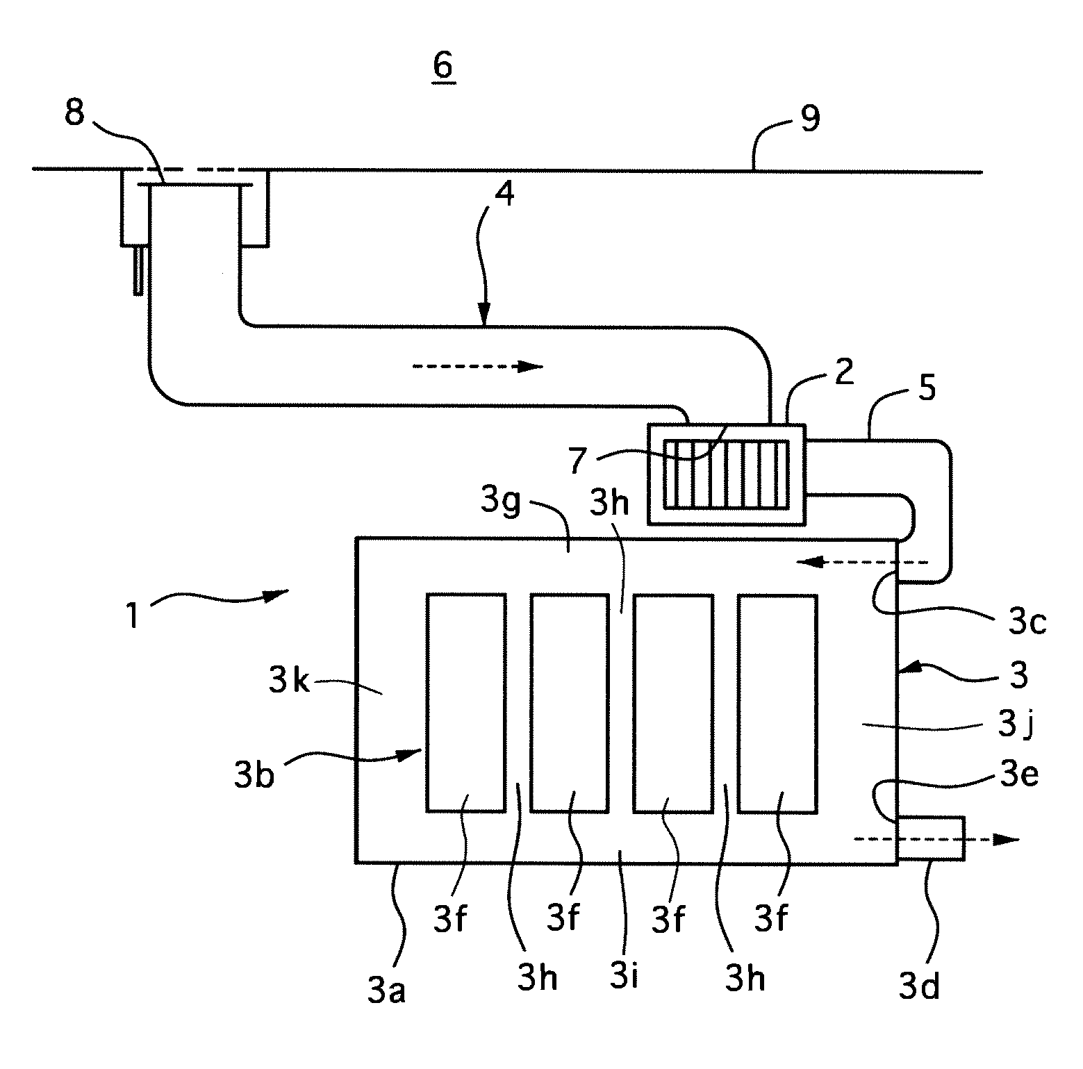
[0020]In the first embodiment, the cooling system of the heat element of the present invention is applied to a cooling device 1 of batteries 3b that are mounted on a hybrid electric vehicle and supplies electric power to a not-shown electric drive motor. The batteries 3b are contained in a battery package 3, which is arranged on both side portions and a lower portion of a luggage compartment located at a rear side of the hybrid electric vehicle.
[0021]The cooling device 1 of the batteries 3b includes a blower fan 2, an intake duct 4, a connecting duct 5, an exhaust duct 3d and others. The intake duct 4 has an opening communicatable with a passenger compartment 6 at one end portion 8 thereof, and is connected with an inlet port of the blower fan 2 at the other end portion 7 thereof. The connecting duct 5 is connected with an outlet port of the blower fan 2 at one end portion thereof, and is connected with an induction port 3c of the battery package 3 at the other end portion thereof. ...
second embodiment
[0050]Next, a cooling system of a heating element of a second embodiment according to the present invention will be described with the accompanying drawings.
[0051]In the cooling system of the second embodiment, there is provided a filter member 20 between a cap 12 and a flange portion 13 of an intake duct 4. The filter member 20 is shaped like a circular cylinder, being fixed by contacting with a circular cylinder portion 12a projected downward from the flange portion 13. The filter member 20 is set to have a diameter smaller than that of a opening hole 10 formed in the rear parcel rack 9 so that the filter member 20 can be taken out toward the passenger compartment through the opening hole 11 The type, material and fixing method of the filter member 20 may be set appropriately.
[0052]The other parts and portions of the cooling system of the second embodiment are constructed similarly to those of the first embodiment.
[0053]In this second embodiment, the air can be sucked in from a pa...
third embodiment
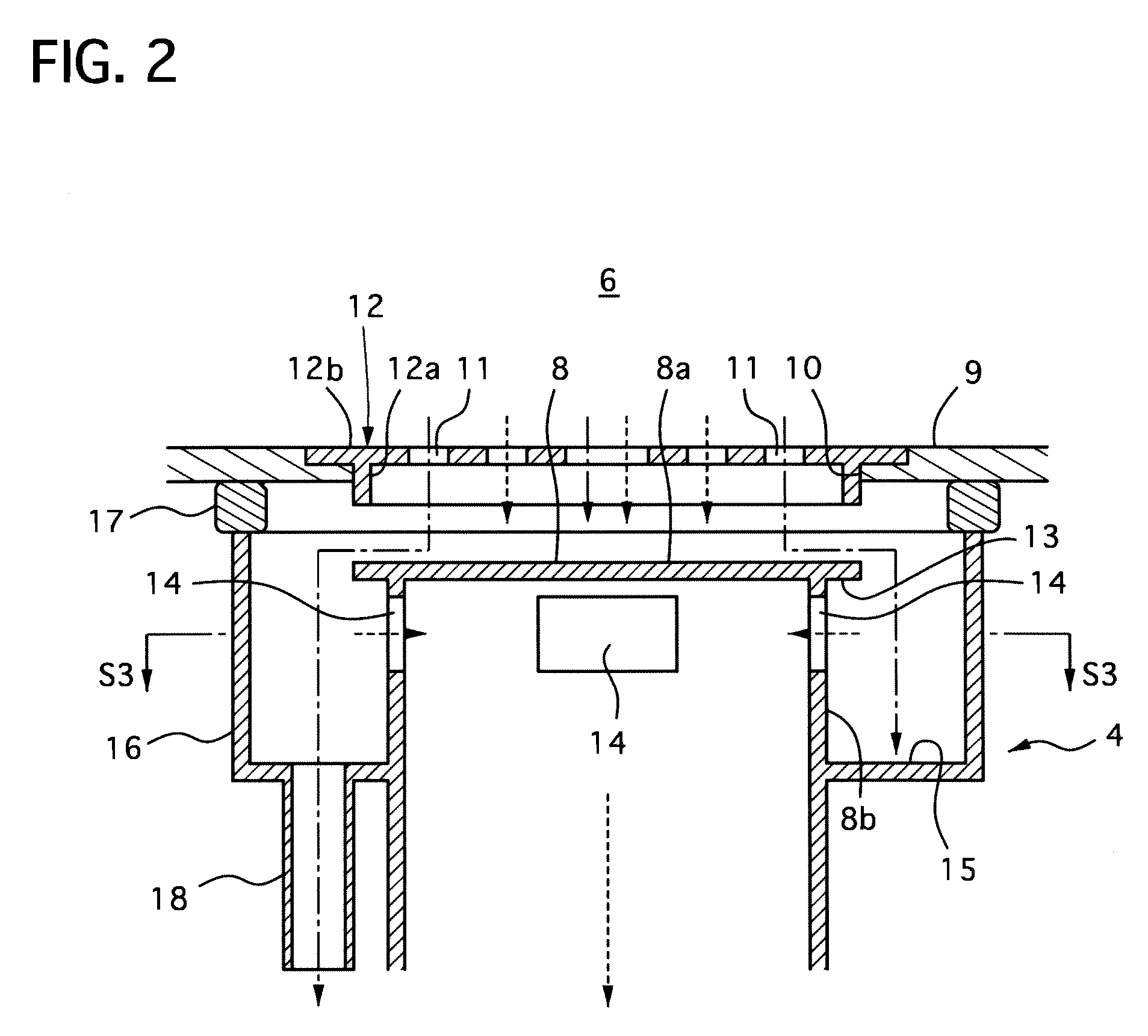
[0058]Next, a cooling system of a heating element of a third embodiment according to the present invention will be described with the accompanying drawings.
[0059]In the cooling system of the third embodiment, one end portion 8 of an intake duct 4 penetrates through an opening hole 10 of a rear parcel rack 9 with a predetermined annular clearance therebetween to project upward therefrom. The one end portion 8 of the intake duct 4 has an opening at its top, and a cap 31 is attached on the end portion by being fitted into a circular cylinder portion 12a of the cap 31. The four opening portion are formed in an outer circumferential side wall portion of the one end portion and a lower surface of the cap 12.
[0060]The cap 12 has a flange portion 31a, which is larger in diameter than the intake duct 4, being bent to extend downward at its outer edge portion. This bending portion of the flange portion 31a is set to extend lower than a lower edge portions of the opening portions 14, and the l...
PUM
 Abstract
Description
Claims
Application Information
 - R&D Engineer
- R&D Manager
- IP Professional
- Industry Leading Data Capabilities
- Powerful AI technology
- Patent DNA Extraction
Browse by: Latest US Patents, China's latest patents, Technical Efficacy Thesaurus, Application Domain, Technology Topic, Popular Technical Reports.
© 2024 PatSnap. All rights reserved.Legal|Privacy policy|Modern Slavery Act Transparency Statement|Sitemap|About US| Contact US: help@patsnap.com