Borehole Cleaning Using Downhole Pumps

Inactive Publication Date: 2009-07-09
SCHLUMBERGER TECH CORP
View PDF26 Cites 21 Cited by
  • Summary
  • Abstract
  • Description
  • Claims
  • Application Information

AI Technical Summary

Benefits of technology

[0020]The method can further comprise injecting gas into the materials in the tubular conv

Problems solved by technology

Additionally, drilling muds used during the drilling process are generally heavier than the reservoir fluid, and tend to also segregate to low-lying areas of the well.
Finally, proppant used during reservoir fracturing operations is not always completely removed.
This high pressure mobilization jetting does increase the Bottom Hole Pressure (BHP) of the reservoir

Method used


Image

  • Borehole Cleaning Using Downhole Pumps
  • Borehole Cleaning Using Downhole Pumps
  • Borehole Cleaning Using Downhole Pumps

Examples


Example

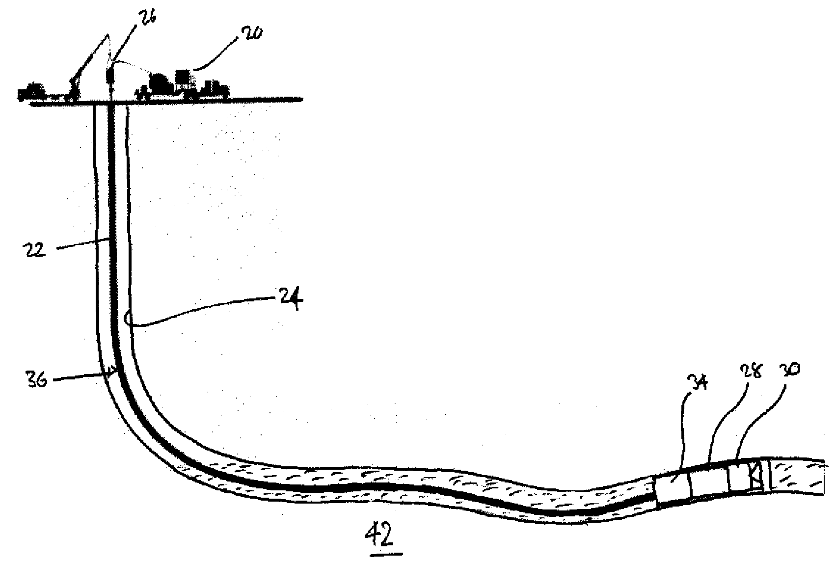
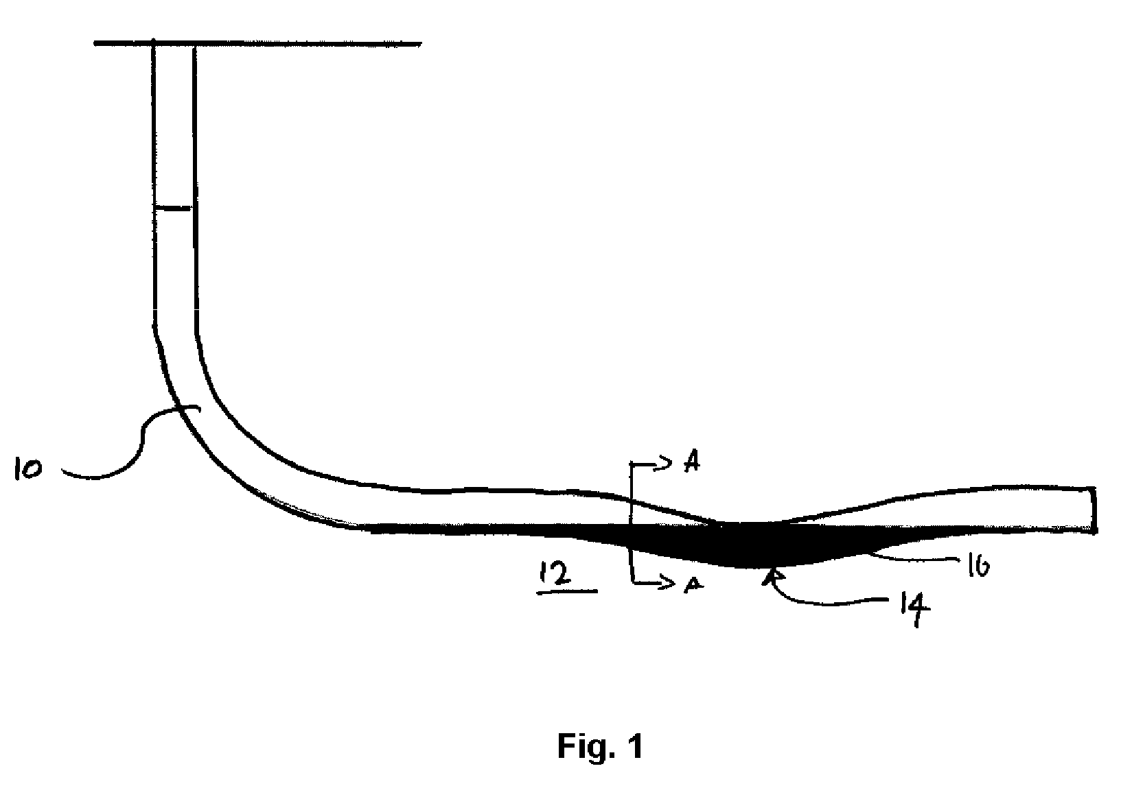
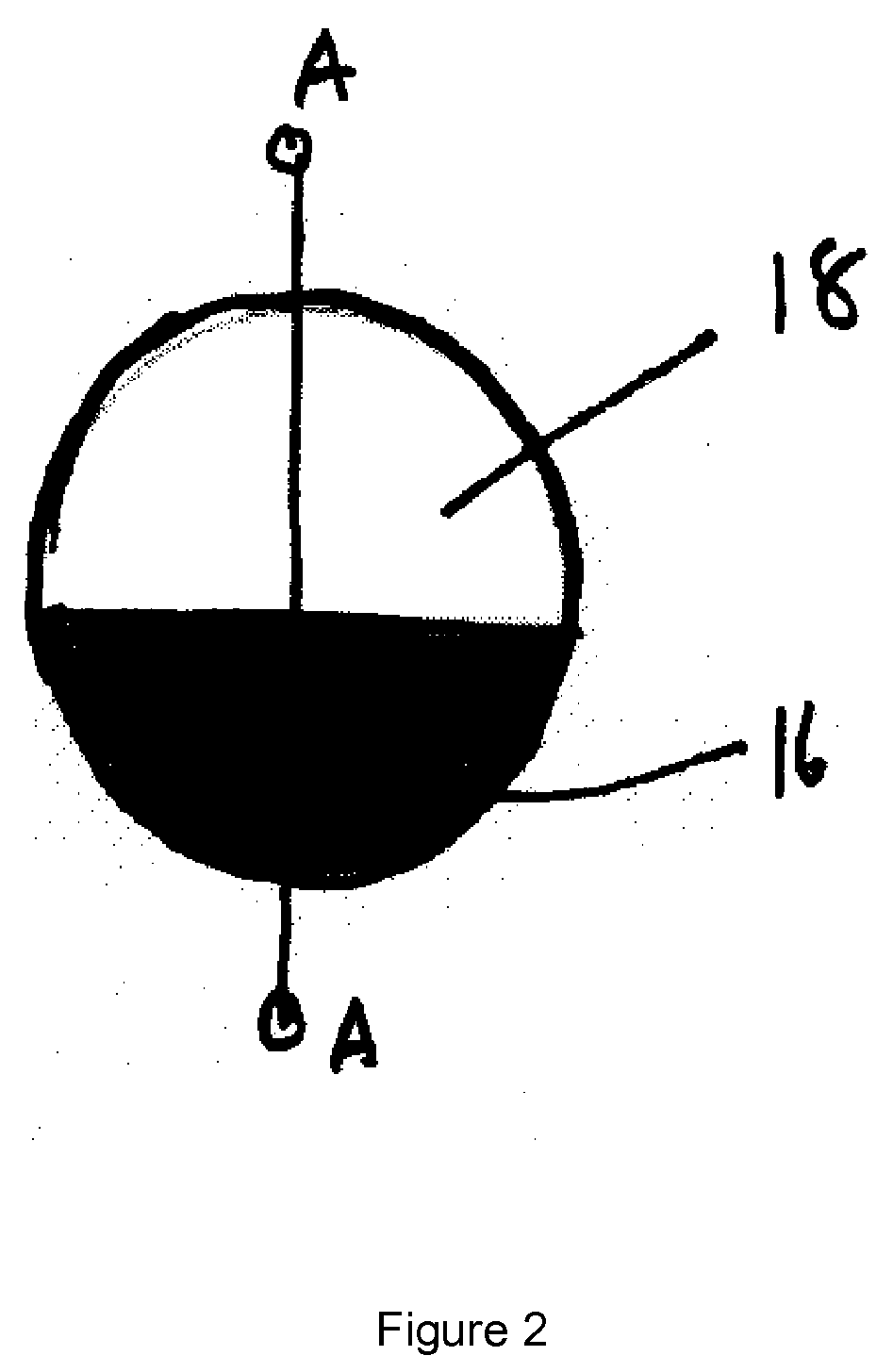
[0032]FIG. 3 shows the use of a system according to an embodiment of the invention in a well of the type shown in FIGS. 1 and 2. The system includes a CT surface system 20 that reels a coiled tubing 22 into the well 24 through surface pressure control equipment 26. An electrically powered motor 28 and pump 30 are located at the end of the CT 22. A power cable 32 (see FIG. 4) runs from the surface to the motor 28 through the CT 22 for protection. The CT 22 also acts as a conduit for fluid / fill mixture removal. The pump 30 is configured to flow in the ‘reverse’ sense, sucking from the lower end and moving the fluid and fill solids upwards through the pump 30 itself and through the CT 22 towards the surface. The CT insulates the well from any pressure increase caused by the pump as it pumps fluid to the surface so avoiding damage to the formation. This can be particularly important in Low BHP reservoirs that can easily be damaged by relatively small increases in wellbore pressure above...


PUM


Abstract

Apparatus for borehole cleaning, comprises: a tubular conveyance for extending from the surface into a borehole to a region to be cleaned; a motor mounted at the end of the tubular conveyance that in use is introduced into the borehole; a pump connected to the motor and having a nozzle; a power cable extending trough the tubular conveyance from the surface to provide power to the motor; the pump being arranged such that, when positioned in the borehole and operated by the motor, the pump withdraws material from the borehole through the nozzle and pumps it into the tubular conveyance to the surface.

Description

TECHNICAL FIELD[0001]Embodiments of the invention relate to systems for borehole cleaning that allow removal of materials in a borehole preventing flow. In particular, embodiments of the invention relate to system for use in wells such as oil and gas wells.BACKGROUND OF THE INVENTION[0002]As oil and gas are extracted from producing wells, sand and heavy oils that have flowed through the perforations accumulate. These are too heavy to flow to the surface along with the usual fluids produced by the well at normal production rates, and tend to accumulate in low-lying areas as shown in FIGS. 1 and 2. Additionally, drilling muds used during the drilling process are generally heavier than the reservoir fluid, and tend to also segregate to low-lying areas of the well. Finally, proppant used during reservoir fracturing operations is not always completely removed. The accumulation problem in particularly severe where the trajectory of the well 10 is at or close to horizontal in the producing...

Claims


Application Information

Patent Timeline
IPC IPC(8): E21B37/00E21B43/12E21B21/00
CPCE21B37/00E21B43/128E21B41/0078
Inventor KOTSONIS, SPYROZEMLAK, WARRENLAVRUT, ERIC
Owner SCHLUMBERGER TECH CORP
Why Eureka
Try Eureka