Light-guide sheet, movable contact unit and switch using the same

a technology of movable contact unit and light guide, which is applied in the direction of luminescent composition, lighting and heating apparatus, chemistry apparatus and processes, etc., can solve the problems of unfavorable light guide, complicated structure, uneven color, etc., and achieve uniform luminescent color, easy to see and uniform lighting, and suppress variations in luminescent colors

Inactive Publication Date: 2009-07-09
PANASONIC CORP
View PDF4 Cites 10 Cited by
  • Summary
  • Abstract
  • Description
  • Claims
  • Application Information

AI Technical Summary

Benefits of technology

[0016]The present invention offers a light-guide sheet that produces uniform luminescent color and provides readily visible and uniform lighting; and a movable contact unit and switch that employ this light-guide sheet. The light-guide sheet of the present invention includes a light-transmissive film substrate, and luminescent protrusions formed at predetermined points on the substrate. At least one of the substrate and each of the luminescent protrusions is colored to a color tone that absorbs yellow light more than blue light. Alternatively, a reflective layer colored to a color tone that absorbs yellow light more than blue light is provided on at least one of the top and bottom faces of the substrate. With either of the above structures, luminescent protrusions at points far from the light-emitting element can also be illuminated in a color tone identical to that of luminescent protrusions near the light-emitting element. Accordingly, variations in luminescent colors can be suppressed, achieving readily visible and uniform lighting.

Problems solved by technology

Illumination of display portions 60B thus results in uneven colors.
However, this results in a complicated and expensive structure.

Method used


Image

  • Light-guide sheet, movable contact unit and switch using the same
  • Light-guide sheet, movable contact unit and switch using the same
  • Light-guide sheet, movable contact unit and switch using the same

Examples


first exemplary embodiment

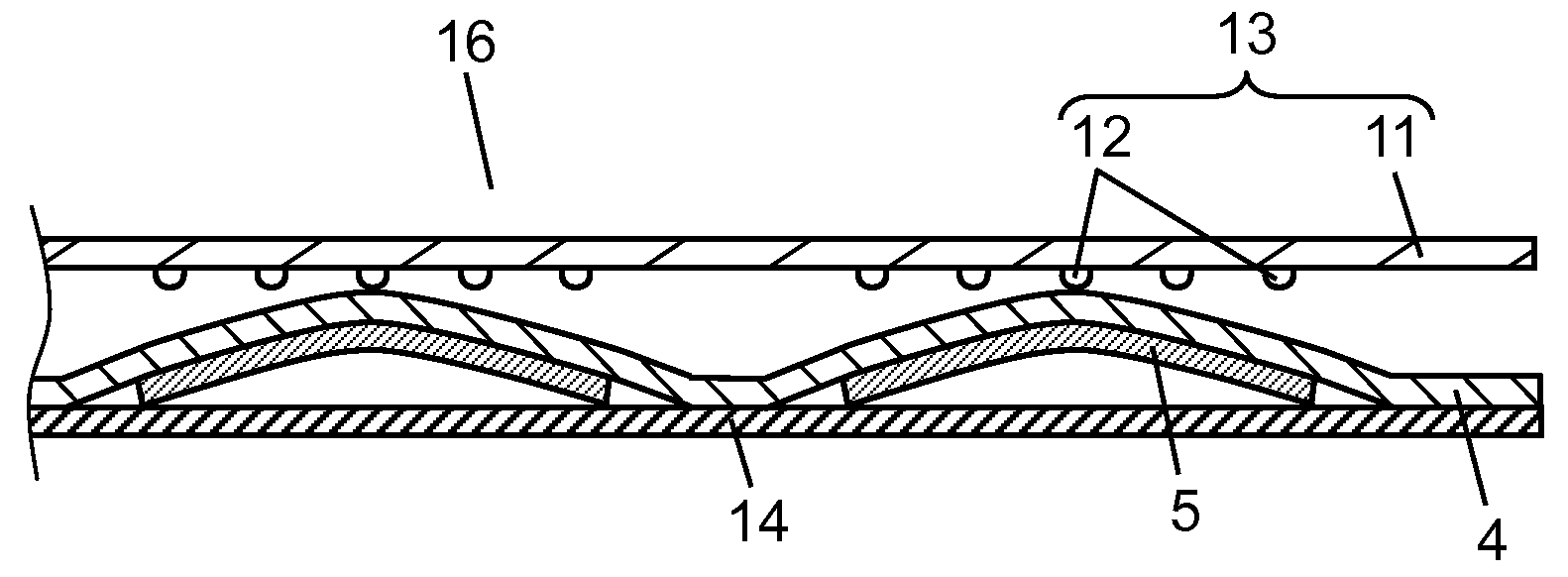
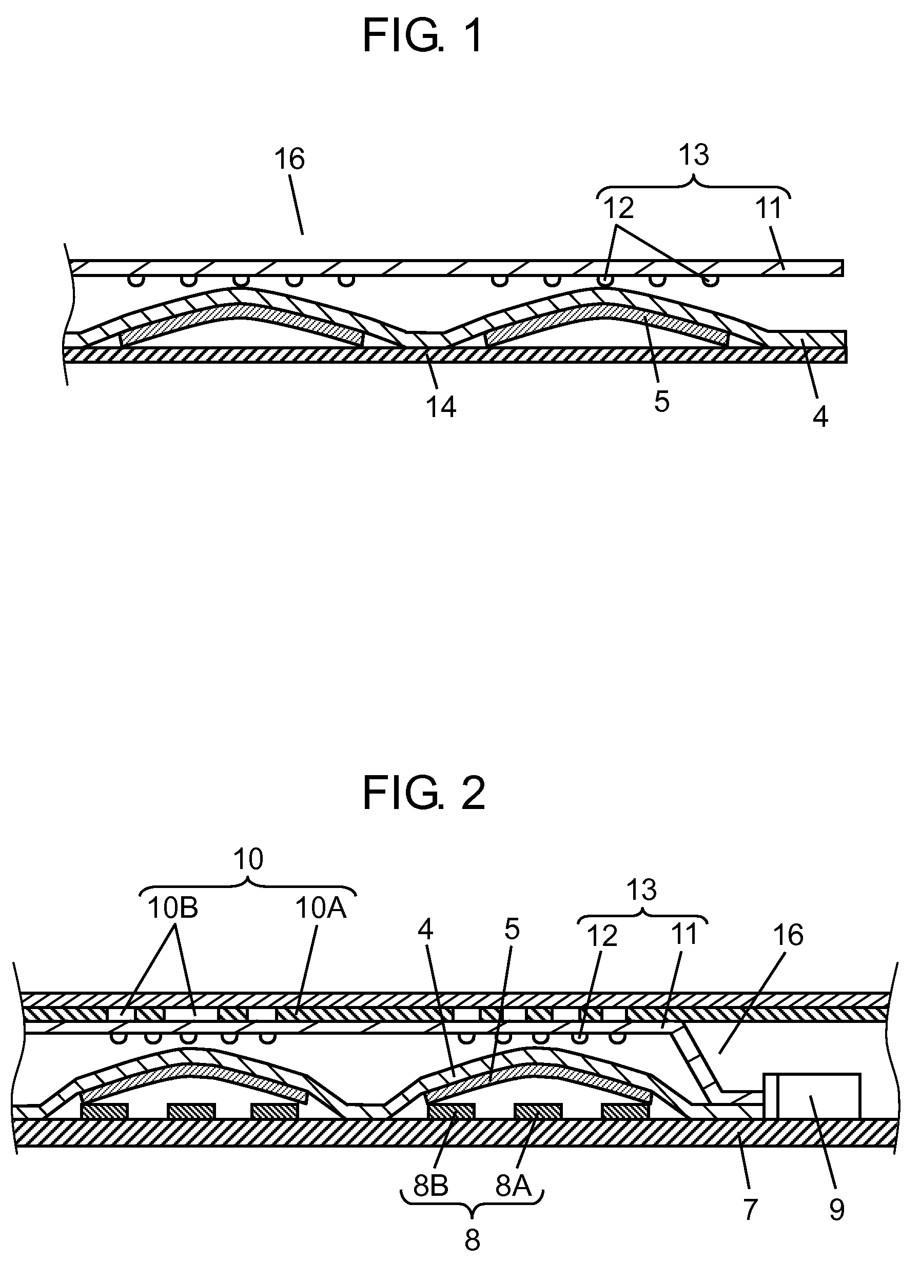
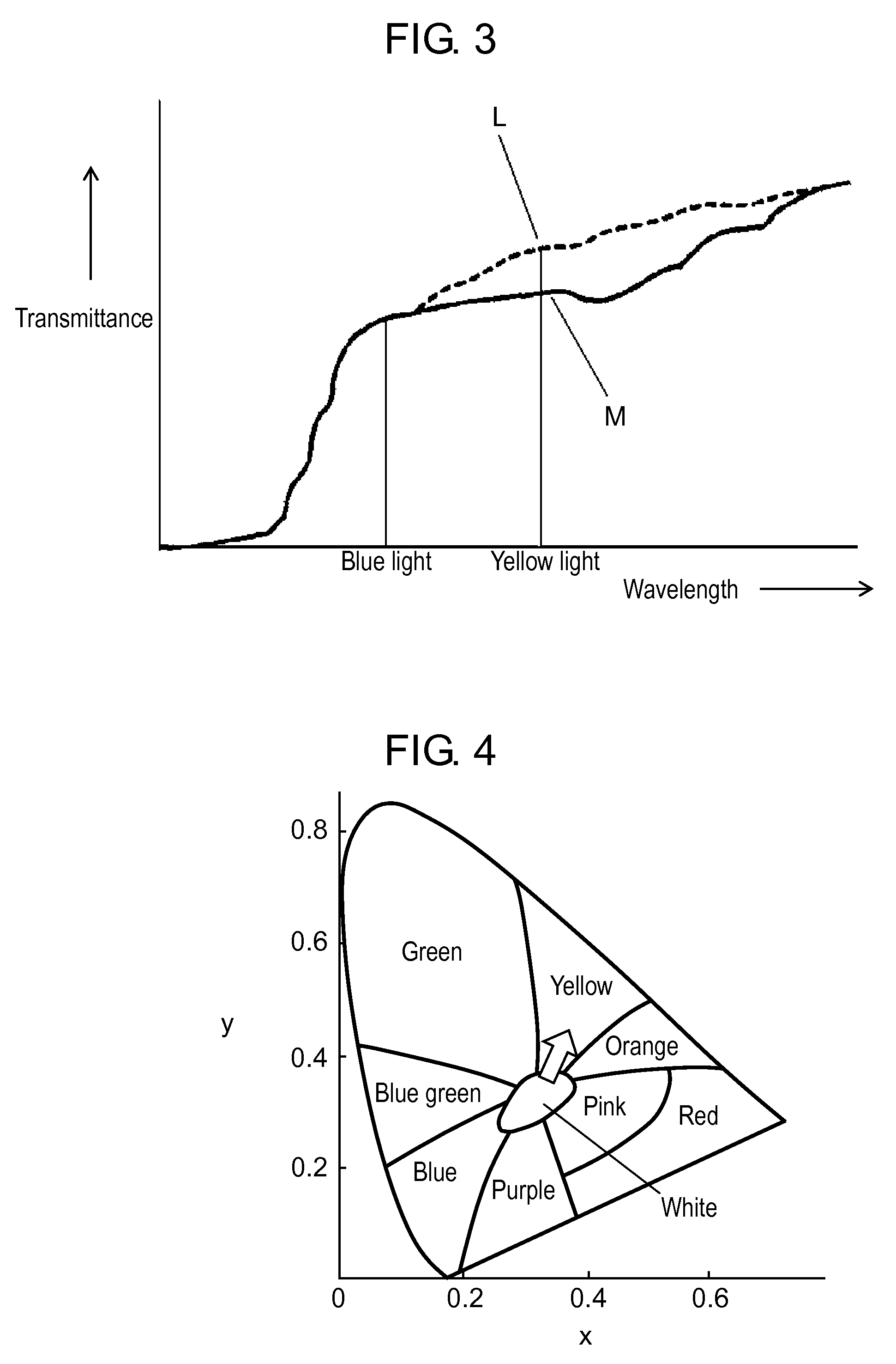
[0030]FIG. 1 is a sectional view of a movable contact unit employing a light-guide sheet in the first exemplary embodiment of the present invention. FIG. 2 is a sectional view of a switch employing the movable contact unit shown in FIG. 1. FIG. 3 is a graph illustrating the relationship between a wavelength and transmittance of the light-guide sheet shown in FIG. 1 and a conventional light-guide sheet. FIG. 4 is an x-y color diagram of CIE1931XYZ color system.

[0031]As shown in FIGS. 1 and 2, movable contact unit 16 includes light-guide sheet 13, film cover sheet 4, and dome-like resilient movable contact 5 made of a thin metal sheet. Light-guide sheet 13 includes light-transmissive film substrate 11 and luminescent protrusions 12 provided at predetermined points on the bottom face of substrate 11.

[0032]Substrate 11 is configured with light-transmissive polyurethane, silicone resin, polystyrene, and the like, and is flexible. Dye or pigment, such as phthalocyanine, indigo, anthraquin...

second exemplary embodiment

[0052]FIG. 5 is a sectional view of a movable contact unit in the second exemplary embodiment of the present invention. FIG. 6 is a plan view of this movable contact unit to which light-emitting element 9 is attached. FIG. 7 is a sectional view of a switch employing this movable contact unit. The second exemplary embodiment differs from the first exemplary embodiment in a point that light-guide sheet 25 includes substrate 21, white luminescent protrusion 22A, and blue luminescent protrusion 22B, instead of substrate 11 and luminescent protrusions 12. Other components are the same as that in the first exemplary embodiment.

[0053]Light-guide sheet 25 includes substrate 21 and luminescent protrusions 22A and 22B. Film substrate 21 is light-transmissive, and is, for example, transparent. In other words, substrate 21 is made of the same main material as substrate 11 in the first exemplary embodiment, but is not colored with dye or pigment.

[0054]Convex and concave light-emitting portions 2...

third exemplary embodiment

[0064]FIG. 8 is a sectional view of a movable contact unit in the third embodiment of the present invention. FIG. 9 is a sectional view of a switch employing this movable contact. The third exemplary embodiment differs from the first exemplary embodiment in a point that substrate 21 is used instead of substrate 11, and reflective layer 27 is provided on light-guide sheet 28A. Other components are the same as that in the first exemplary embodiment.

[0065]Light-guide sheet 28A includes substrate 21, luminescent protrusions 12, and reflective layer 27. Substrate 21 is the same as that used in the second exemplary embodiment, and luminescent protrusions 12 are the same as that used in the first exemplary embodiment. Accordingly, description of their details is omitted. Movable contact unit 29 employs light-guide sheet 28A.

[0066]Reflective layer 27 is formed on the top face of substrate 21 typically by printing. Reflective layer 27 is formed typically of acryl, polyester, epoxy, or silico...


PUM

PropertyMeasurementUnit
Outer lengthaaaaaaaaaa
elastic modulusaaaaaaaaaa

Abstract

A light-guide sheet includes a light transmissive film substrate, and luminescent protrusions formed at predetermined points on the substrate. At least one of the substrate and each of the luminescent protrusions is colored to a color tone that absorbs yellow light more than blue light. Alternatively, a reflective layer colored to a color tone that absorbs yellow light more than blue light is provided on at least one of the top and bottom faces of the substrate.

Description

BACKGROUND OF THE INVENTION[0001]1. Field of the Invention[0002]The present invention relates to a light-guide sheet used for mainly operating electronic devices, and a movable contact unit and a switch employing the light-guide sheet.[0003]2. Background Art[0004]Recent electronic devices, typically mobile information terminals such as mobile phones, increasingly adopt light-emitting diodes or electroluminescent (EL) elements for lighting their control panels. This is to facilitate the identification and operation of buttons and display sheets, even in the dark. Movable contact units and switches that can be illuminated for easier visibility are also in demand for use in these devices.[0005]A conventional movable contact unit and a switch are described next with reference to FIG. 11. FIG. 11 is a sectional view of the conventional switch. To facilitate understanding of the structure, dimensions are partially enlarged in FIG. 11. This switch includes movable contact unit 56, wiring b...

Claims


Application Information

Patent Timeline
Patent Type & Authority Applications(United States)
IPC IPC(8): H01H9/16C09K11/00
CPCH01H13/7006H01H13/83H01H2219/062H01H2219/056H01H2219/06H01H2219/044
Inventor TATEHATA, NAOKICHIKAHISA, YOUSUKEAISAKA, TSUTOMUTANABE, KOJIWATANABE, HIROTOSHI
Owner PANASONIC CORP
Why Eureka
Try Eureka