Fastening Spider and Method of Fastening

a technology of fastening devices and spiders, which is applied in the field of fastening spiders, can solve the problems of ineffective fastening of fastening devices, significant wear on the surface over which the material moves, and relatively complicated and expensive in both construction and installation, and achieves the effects of simple construction, easy and inexpensive manufacturing, installation and replacement, and greater holding for

Active Publication Date: 2009-07-09
METSO OUTOTEC (FINLAND) OY
View PDF13 Cites 8 Cited by
  • Summary
  • Abstract
  • Description
  • Claims
  • Application Information

AI Technical Summary

Benefits of technology

[0018]A general advantage of the invention according to this alternative is that it will be possible to make a fastening spider of the above type which has a simple construction and is easy and inexpensive to manufacture, install and replace.
[0019]A special advantage is that the fastening spider effectively holds wear-resistance lining elements to a support surface. This is achieved by the above-described shape distributing clamping force, via the mounting portion, uniformly in the legs of the fastening spider. In this way, the holding force of the spider legs against the wear-resistant lining element will be greater in the outer portions of the leg, compared with prior-art technique. Traditionally, a greater holding force occurs in portions close to the mounting portion, for instance because the spider legs tend to be bent in clamping of the fastening spider, which is one of the effects that are counteracted by the described invention.
[0020]It should be noted that that part of the wear-resistant lining element which is clamped between a spider leg and a support surface is often made of an elastomeric material which can partly yield to or be depressed by forces applied. This also promotes the effect and advantage that the force exerted by the spider is more uniformly distributed in the legs of the fastening spider.
[0021]Another advantage is reduced noise as material in the form of pieces or particles moves over a wear-resistant lining element which is fastened according to the invention.
[0022]The fastening spider may, in the mounting positioning of the mounting portion, be arranged to be in contact with the support surface or the wear-resistant lining element, merely using the outer portion on the underside of the leg.
[0023]The fastening spider may also, in the mounting positioning of the mounting portion, be arranged to be in contact with the support surface or the wear-resistant lining element, using the underside of the mounting portion.

Problems solved by technology

This is common in handling materials such as sand, gravel, stone, ore etc. which, with or without water being added, cause significant wear on the surfaces over which the material moves.
A general drawback of existing fastening devices and methods of fastening wear-resistant lining elements to a surface is that they are relatively complicated and expensive in terms of both construction and installation.
A further drawback is that the fastening devices do not always effectively fasten the wear-resistant lining elements to the support surface, or that the fastening, when mechanically affected, is not capable of holding the wear lining in place.
This results in production troubles on the one hand since a loose wear lining must be fastened again and, on the other hand, because they are damaged more easily and thus must be replaced prematurely.
The problem in connection with this fastening element is, among other things, that the wear-resisting lining element is not sufficiently effectively fastened to the support surface.
This results in operating troubles and, thus, increased costs in the contexts where the element is used.
Although the wear lining according to EP 1 058 801 is a multipurpose lining and effective, it happens that the wear-resistant lining elements do not sufficiently effectively abut against the support surface.
As mentioned above, this causes additional costs in the form of stoppage and the necessary replacement of damaged wear-resistant lining elements.
Summing up, the technicians have problems with increased costs in the form of stoppage, the necessary replacement of damaged wear-resistant lining elements, increased wear etc.
An important factor is here that wear-resistant lining elements do not sufficiently effectively abut against a support surface on which they are mounted.
A further problem is that increased noise occurs as material moves over an insufficiently fastened wear-resistant lining element.

Method used


Image

  • Fastening Spider and Method of Fastening
  • Fastening Spider and Method of Fastening
  • Fastening Spider and Method of Fastening

Examples


Embodiment Construction

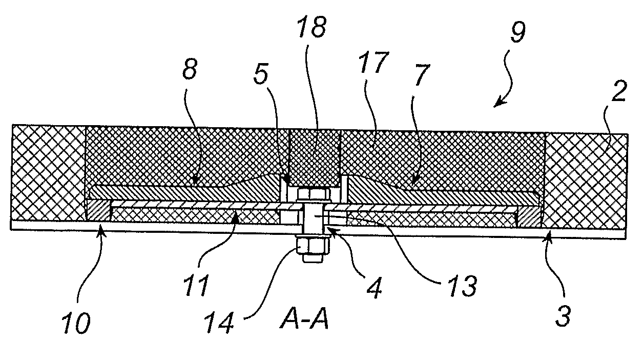
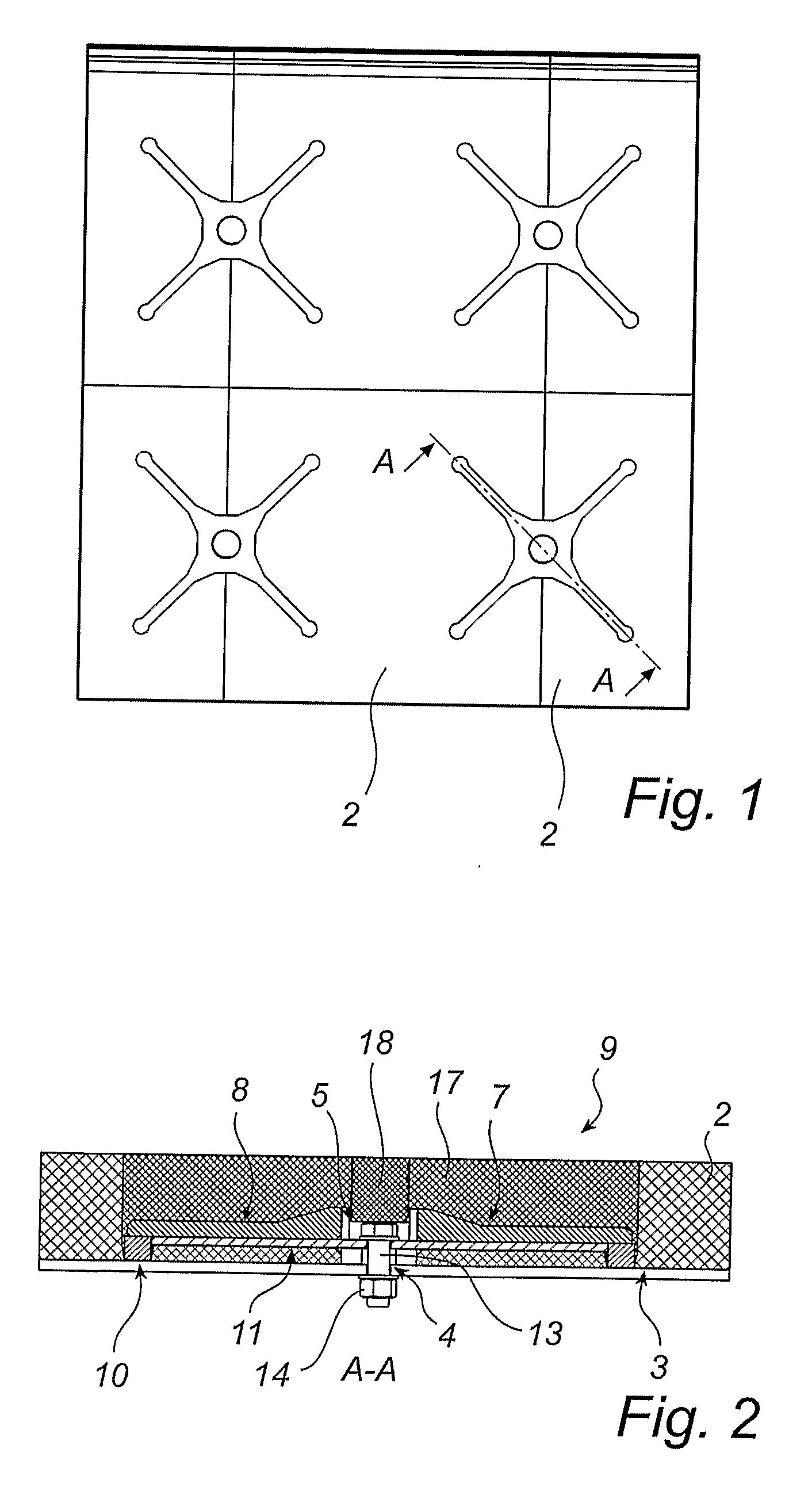
[0047]FIGS. 1 and 2 illustrate a wear lining 19 with a fastening spider 1 which fastens two wear-resistant lining elements 2 to a support surface 3. The support surface 3 has a mounting point 4 in the form of a through hole.

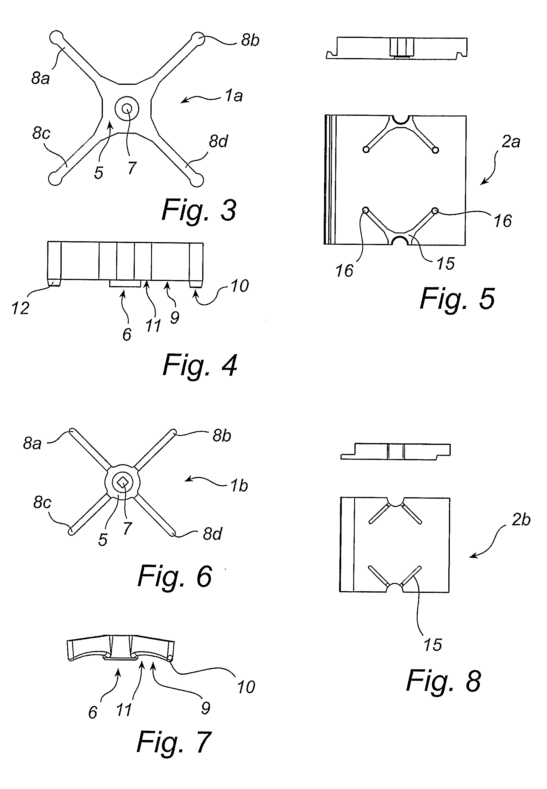
[0048]FIGS. 3 and 4 illustrate the fastening spider 1a which has a central mounting portion 5. The mounting portion 5 has an underside 6, a through hole 7 and four projecting legs 8a-8d. Each leg has an underside 9 which in turn has an outer portion 10 and an inner portion 11. In this embodiment, the outer portion 10 has a supporting point 12 directed towards the support surface 3. The fastening of the fastening spider 1a to the mounting point 4 occurs by means of a bolt 13 which extends through the mounting point 4 of the support surface and the hole 7 of the mounting portion. The bolt 13 is tightened by means of a nut 14.

[0049]FIG. 5 illustrates the wear-resistant lining element 2a which is intended for the fastening spider 1a according to FIG. 3. The wear-resi...


PUM


Abstract

A fastening spider (1) and a method of fastening a wear-resistant lining element (2) to a support surface (3), over which wear-resistant lining element (2) material in the form of pieces or particles is intended to move. The fastening spider (1) comprises a mounting portion (5) for mounting positioning and clamping to the support surface (3) and at least one leg (8a-8b) projecting from the mounting portion (5) and having an underside for holding the wear-resistant lining element (2) to the support surface (3). The underside of the leg has an outer portion (10) and an inner portion (11), the inner portion (11) being positioned closer to the mounting portion (5) than the outer portion (10). The outer portion (10) is, at least in the mounting positioning of the mounting portion, positioned closer to the support surface (3) than the inner portion (11).

Description

FIELD OF THE INVENTION[0001]The present invention relates to a fastening spider for fastening a wear-resistant lining element to a support surface, over which wear-resistant lining element material in the form of pieces or particles is intended to move. The fastening spider comprises a mounting portion for mounting positioning and clamping to the support surface and at least one leg projecting from the mounting portion and having an underside for holding the wear-resistant lining element to the support surface. The underside of the leg has an outer portion and an inner portion, the inner portion being positioned closer to the mounting portion than the outer portion.[0002]The invention also relates to a wear lining and a method of fastening a wear-resistant lining element to a support surface, over which wear-resistant lining element material in the form of pieces or particles is intended to move.BACKGROUND ART[0003]There are many different types of fastening means for fastening wear...

Claims


Application Information

Patent Timeline
Patent Type & Authority Applications(United States)
IPC IPC(8): A47B96/06A44B21/00A44B99/00
CPCB02C17/22B60R13/01Y10T24/44017B65G11/16E04F13/0835B61D17/18B02C17/225E04F13/0837
Inventor GRONVALL, LARS
Owner METSO OUTOTEC (FINLAND) OY
Why Eureka
Try Eureka