Tip for an earth working roll

a technology for earthwork and tips, applied in the direction of dislodging machines, pedestrian/occupant safety arrangements, vehicular safety arrangements, etc., can solve the problem that the wear cap wears out well before the base, and achieves the effect of shortening the useable life of the tips, reducing costs, and increasing wear and drag

Active Publication Date: 2009-07-09
ESCO GRP LLC
View PDF56 Cites 37 Cited by
  • Summary
  • Abstract
  • Description
  • Claims
  • Application Information

AI Technical Summary

Benefits of technology

[0011]In another aspect of the invention, the front portion of the tip has side relief in its penetration profile for increased reduction in wear and drag. The penetration profile is the transverse configuration taken in the general direction of the material flow relative to the tip during operation of the machine.
[0012]It has been determined that the intensive wearing effects associated with the operation of a driven roll is experienced primarily on the front end of the tip and in the primary direction of the flow of the material relative to the movement of the tip. By providing side relief in this portion and in the direction of the primary flow of the material, hardfacing need only be provided on this front end without shortening the useable life of the tips. The use of less hardfacing reduces costs and eases manufacturing.
[0013]In another aspect of the invention, the tip has a leading surface inclined upward to the front surface to define a foremost impact corner for striking the rock and other earthen material. The intersection of the front and leading surfaces to define a corner as the foremost leading portion of the t

Problems solved by technology

As a result, the wear cap we

Method used


Image

  • Tip for an earth working roll
  • Tip for an earth working roll
  • Tip for an earth working roll

Examples


Embodiment Construction

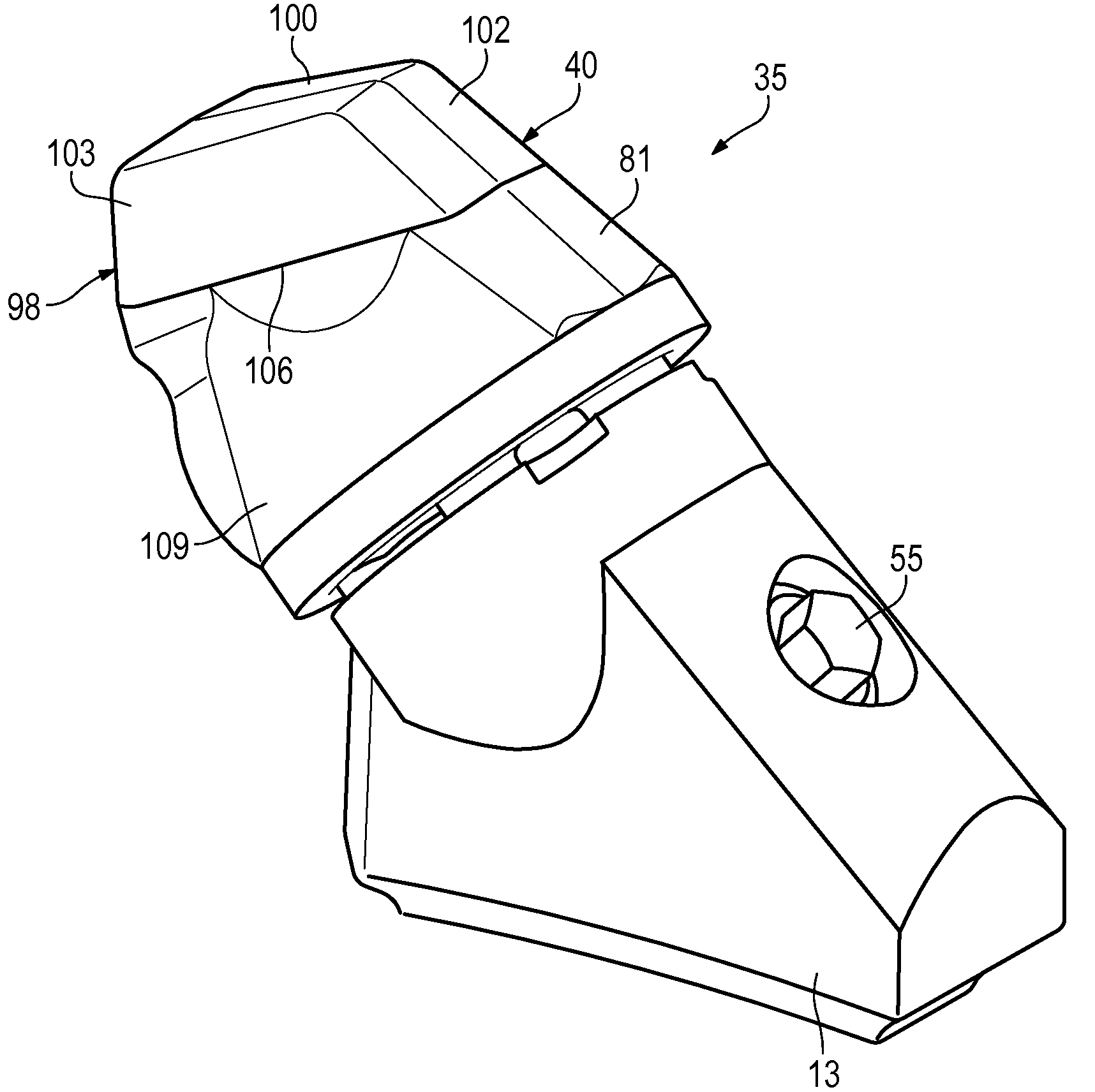
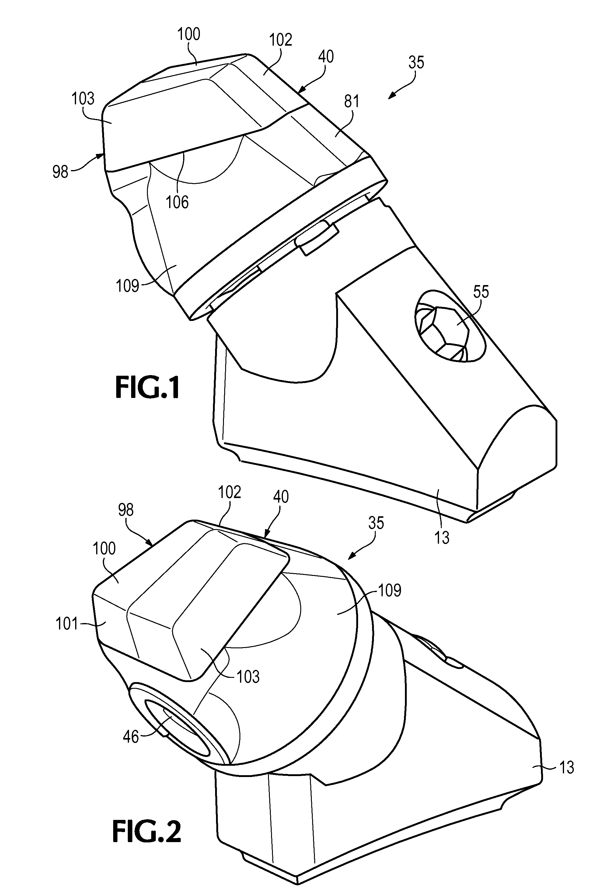
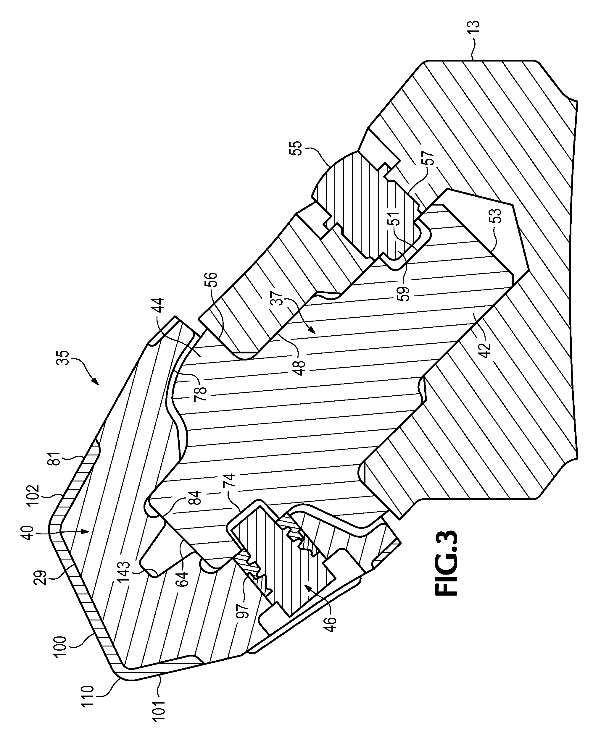
[0071]The present invention pertains to tips for an earth working roll or roller such as used in roll crushers, surface miners, milling machines and the like. The tips are at times described in this application in relative terms such as upper, lower, front, rear, vertical, horizontal and the like. These relative directional terms are not essential to the invention. The orientations of the tips on an earth working roll change considerably during operation. Accordingly, the use of these relative terms is not to be limiting of the invention, but rather to ease the description. Also, the tips in this application are described primarily in the context of a double roll crusher. Nevertheless, the invention is not limited to this operation. Tips in accordance with the invention are also suitable for use in conjunction with other earth working machines involving the use of driven rolls with tips such as single roll crushers, scroll crushers, surface miners, underground mining machines, milli...


PUM


Abstract

A tip for use on an earth working roll for mining, construction and public works machines such as crushers, surface miners, milling machines and the like includes a working end provided with side relief to reduce drag and wearing, require less power to drive the rolls, and lengthen the usable life of the tip. The working end can also have a generally flat front surface to improve the yield in a crushing or other similar operation. The tip includes a base and a wear cap releasably secured together by a retainer.

Description

FIELD OF THE INVENTION[0001]The present invention pertains to a tip for an earth-working roll such as used in a roll crusher, surface miner, underground mining machines, milling machine and the like.BACKGROUND OF THE INVENTION[0002]A number of machines involved in mining, construction and public works use rolls that are driven for the crushing, mining, milling and the like of earthen materials. These earth working rolls include an array of tips to engage the material to be worked. The tips are releasably secured to holders attached to the roll at various locations. The tips are wear parts that are replaced after a certain length of use.[0003]As one example, earth working tips can be provided in a roll crusher for the crushing of earthen material in a mining operation. In a typical operation (FIG. 53), the mined material 1 is dumped into a chute 3 and directed onto a conveyor 5 for transport to a roll crusher 7. The roll crusher 7 is a double roll crusher, which includes a pair of op...

Claims


Application Information

Patent Timeline
IPC IPC(8): E21C25/10E21C41/00
CPCE21C2035/1806E21C35/1933E21C35/1831E02F9/28
Inventor MORRIS, RAY J.CARPENTER, CHRISTOPHER M.FLECK, ROBERT S.CHEYNE, MARK A.
Owner ESCO GRP LLC
Why Eureka
Try Eureka