Bearing device for main electric motor for vehicle

a technology for electric motors and bearing devices, which is applied in the direction of machines/engines, mechanical equipment, drip or splash lubrication, etc. it can solve the problems of misty oil taken up by the oil take-up disk, leakage of oil into or out of the device, and increase the pressure difference between the inside and outside of the main electric motor, so as to reduce maintenance work and reduce the deterioration of the bearing and lubricating oil

Active Publication Date: 2009-07-09
TOYO DENKI SEIZO KK
View PDF6 Cites 8 Cited by
  • Summary
  • Abstract
  • Description
  • Claims
  • Application Information

AI Technical Summary

Benefits of technology

[0014]In accordance with the present invention the following effect can be expected;
[0015](1) the annular first oil return chamber and the annular second oil return chamber are provided on the bearing cover, the second oil return chamber and the oil supply chamber are communicated with each other through the oil return hole, the pipe extending to the oil return hole is provided, the opening of the pipe being made to face the oil take-up disk provided in the oil return chamber with the fine gap, so that it is possible in the main electric motor for vehicle including the bearing device of the oil lubricating structure to prevent the leakage of the oil in the bearing device to the outside and keep lubrication performance of the bearing excellent. It is therefore possible for the present invention to contribute to the reduction of the deterioration of a bearing and lubricating oil and the reduction of maintenance work of the main electric motor for vehicle.
[0016](2) The oil thrower plate is provided at a location above the oil take-up disk separated with a fine gap from the disk, so that it is possible to bank up oil taken up just above the rotor shaft for ease of inflow thereof.
[0017](3) The oil supply hole is provided above the annular bearing press provided between the oil supply chamber and the bearing for guiding the lubricating oil taken up with the oil take-up disk in the direction of the bearing, so that it is possible to guide the oil stored around the outer circumference of the bearing press through the bearing box into the bearing and make the lubrication state of the bearing excellent.

Problems solved by technology

However, such a constitution of sealing with the labyrinth structure as described above suffers from the leakage of oil to the outside of the device.
More specifically, a pressure difference between the inside and outside of the main electric motor is increased owing to temperature rise in the main electric motor for vehicle upon the use of the same, a pressure change in the main electric motor by the rotation of a rotor, and changes in weather and dates upon the use of the main electric motor For this, oil taken up by the oil take-up disk becomes mist and might leak into or out of the device through clearance of the labyrinth.
This complicates the structure and makes it difficult to effectively supply the lubricating oil depending on the shape and disposition of the passage.

Method used


Image

  • Bearing device for main electric motor for vehicle
  • Bearing device for main electric motor for vehicle
  • Bearing device for main electric motor for vehicle

Examples


Embodiment Construction

[0044]Preferred embodiments of the present invention will be described with reference to the accompanying drawings,

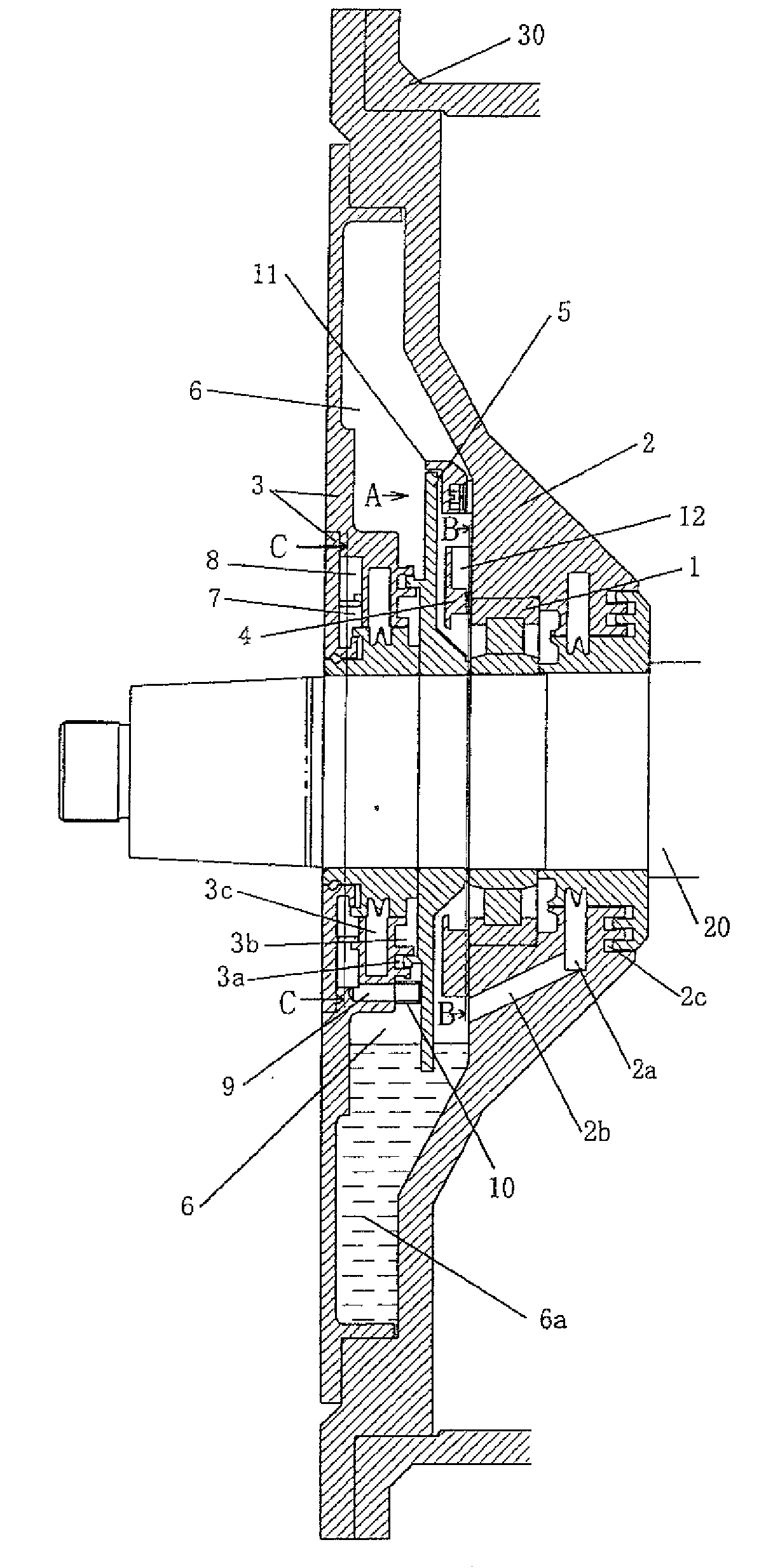
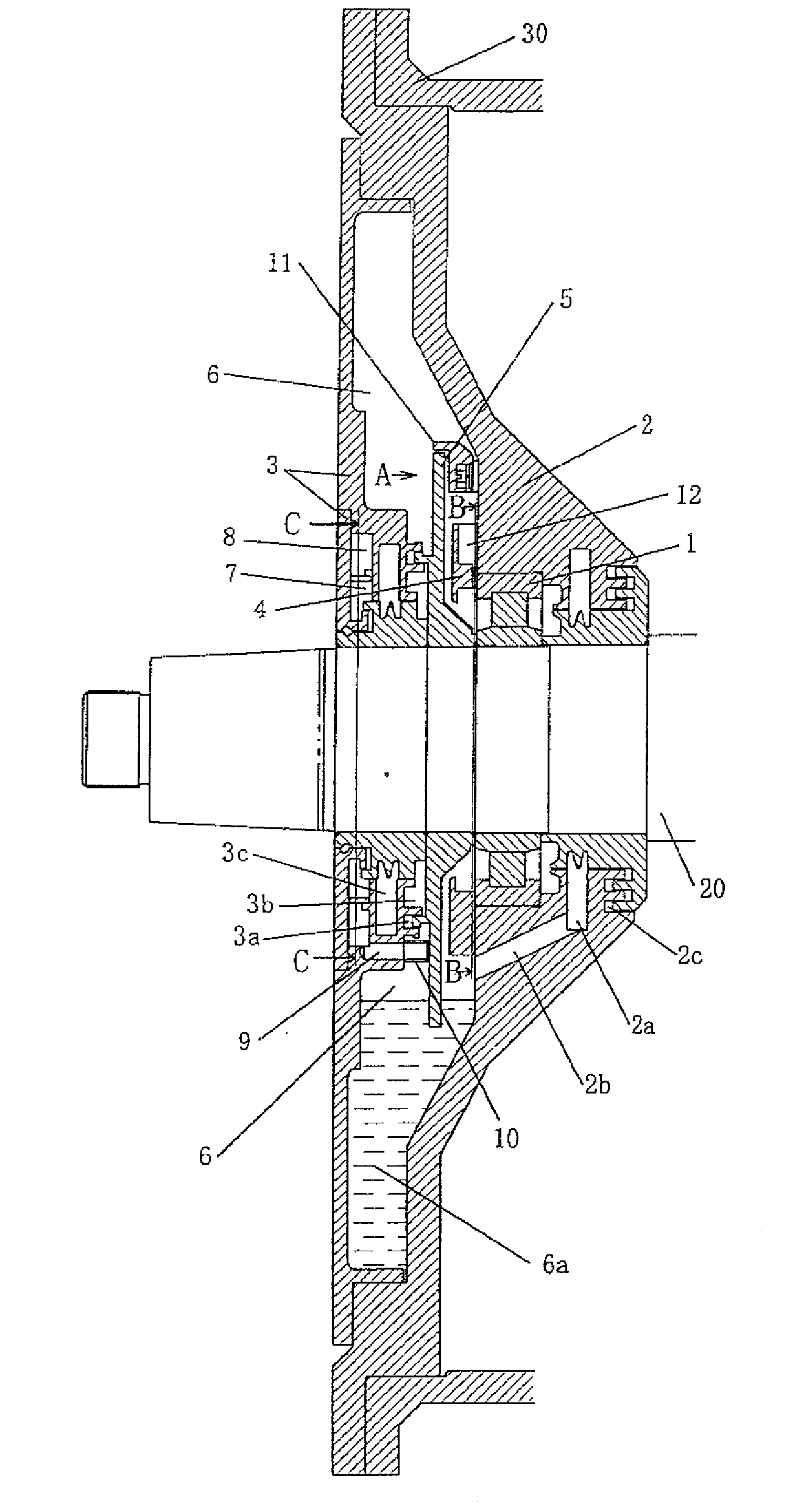
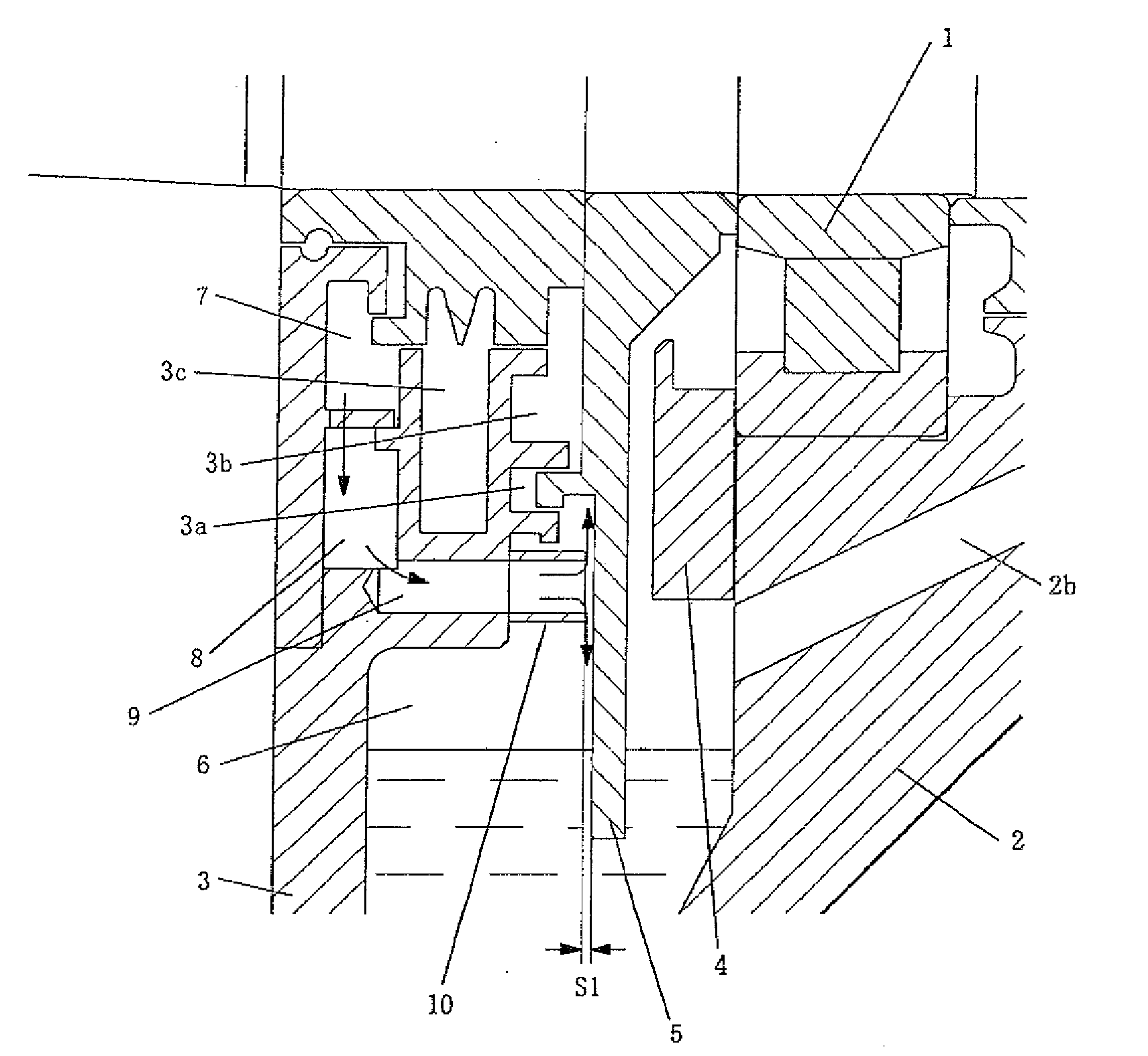
[0045]FIG. 1 is a view in cross section illustrating a bearing device of a main electric motor for vehicle in an embodiment of the present invention, in which although one bearing device of the main electric motor for vehicle is illustrated, the main electric motor for vehicle includes a pair of bearing devices of the same construction. FIG. 2 is a cross sectional view , enlarged in part, illustrating a portion of the present invention. In the same figures, designated at 6 is an oil supply chamber, in a lower portion of which lubricating oil is stored. That portion is called an oil storage chamber 6a. Designated at S is an oil take-up disk which is mounted on a rotor shaft 20 and a part of a lower side of which is immersed in oil in the oil storage chamber 6a. As the oil take-up disk 5 is rotated together with the rotor shaft, the oil in the oil storage chamber 6a is ta...


PUM


Abstract

Oil is supplied to bearing 1 and returned to oil storage chamber 6a via chamber 2a and pipe 2b. First oil return chamber 8 and second oil return chamber 7 communicate via a hole, and second oil return chamber 7 communicates with oil supply chamber 6 via oil return hole 9. The opening of the extension pipe 10 of oil return hole 9 has a small gap, to result in negative pressure in extension pipe 10. The negative pressure sucks the oil leaking from between bearing cover 3 and rotor shaft 20. The oil leaking is suppressed, keeping the supply of the lubricating oil to the bearing excellent.

Description

TECHNICAL FIELD OF THE INVENTION[0001]The present invention relates to a structure of a bearing device for electric motor for vehicle, and more particularly to a main electric motor for vehicle suppressed in leakage of lubricating oil to the outside of the device.BACKGROUND OF THE INVENTION[0002]Although grease is used in prior art for lubrication of a bearing of a main electric motor for vehicle, development and researches of bearing structures of oil lubrication have been advanced for the purpose of saving of maintenance because a cracking period is elongated. For bearing structures of oil lubrication in a main electric motor for vehicle there are known those listed in Japanese Unexamined Patent Application Publications No.62-75195, No.2003-23747 for example. In a bearing structure described in the '195 and '747 Applications, lubricating oil stored in an oil supply chamber is taken up by a rotation plate mounted on a rotary shaft and is supplied to a bearing box. In the prior art ...

Claims


Application Information

Patent Timeline
Patent Type & Authority Applications(United States)
IPC IPC(8): H02K5/15
CPCF16C33/664F16C33/6666F16C33/80H02K5/1732H02K9/19F16C33/6685
Inventor IBARAKI, TAMOTSU
Owner TOYO DENKI SEIZO KK
Why Eureka
Try Eureka