Stator Bar Components with High Thermal Conductivity Resins, Varnishes, and Putties

a stator bar and high thermal conductivity technology, applied in the direction of windings, inorganic insulators, winding insulation materials, etc., can solve the problems of reducing the thermal resistance of stator bars and the temperature differential between respective conductors, and achieve high thermal conductivity

Inactive Publication Date: 2009-07-09
GENERAL ELECTRIC CO
View PDF15 Cites 17 Cited by
  • Summary
  • Abstract
  • Description
  • Claims
  • Application Information

AI Technical Summary

Benefits of technology

[0005]The present application thus describes a stator bar or any similar type of armature coil. The stator bar may include a conductor, a l

Problems solved by technology

Specifically, reducing the thermal resistance of the stator bar components may reduce the tempera

Method used


Image

  • Stator Bar Components with High Thermal Conductivity Resins, Varnishes, and Putties
  • Stator Bar Components with High Thermal Conductivity Resins, Varnishes, and Putties
  • Stator Bar Components with High Thermal Conductivity Resins, Varnishes, and Putties

Examples


Embodiment Construction

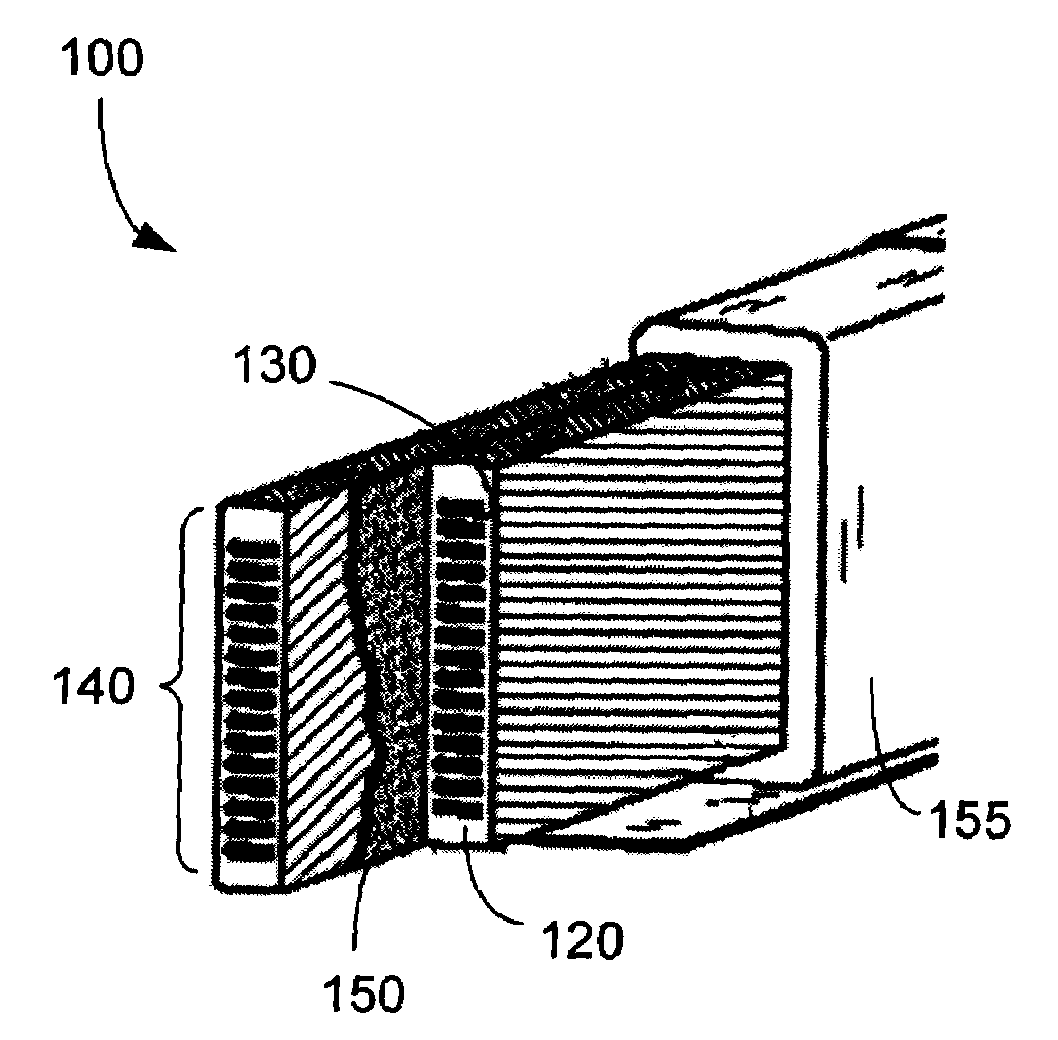
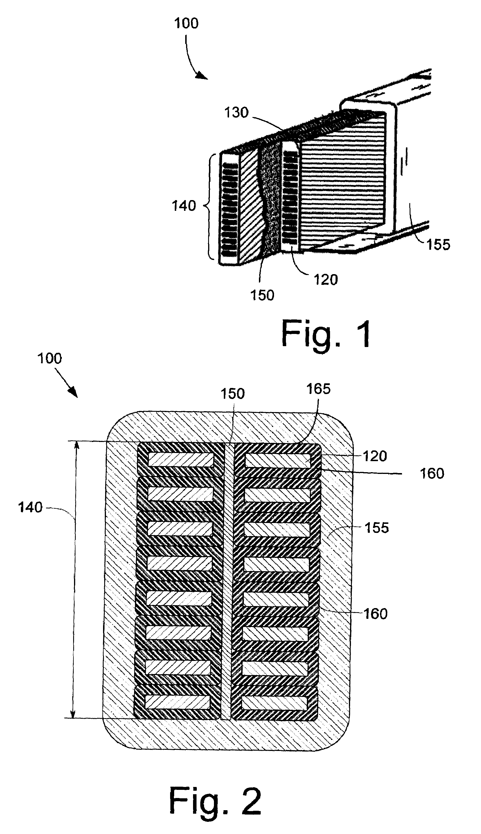
[0014]Referring now to the drawings, in which like numerals refer to like elements throughout the several views, FIG. 1 shows a stator bar 100 as is described herein. The stator bar 100 may be used with electrical machines as is known in the art. An electrical machine generally may have multiple stator bars 100. The multiple stator bars 100 may be identical and may be disposed upon or about each other as is known.

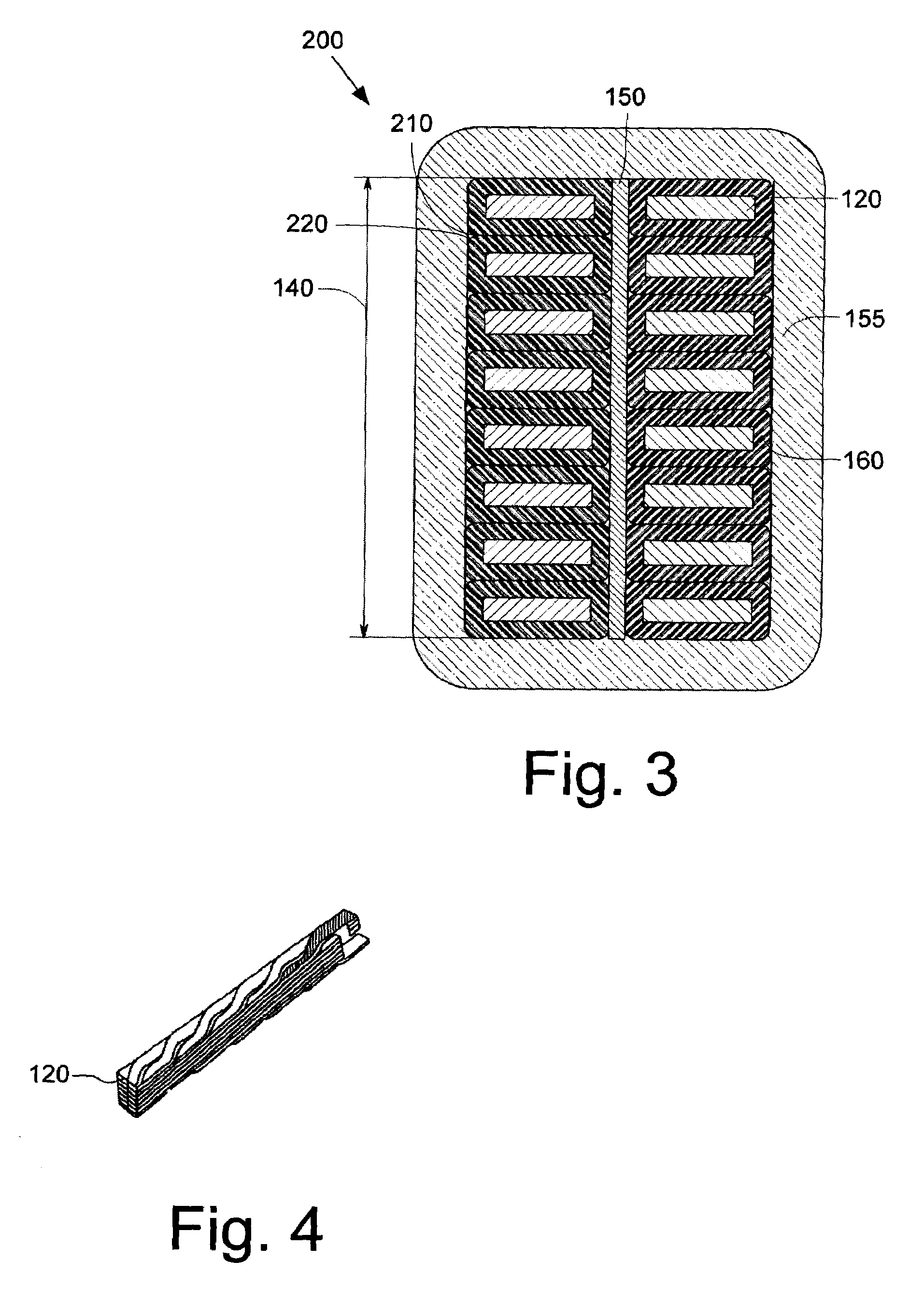
[0015]Generally described, each stator bar 100 may include a number of conductors 120. The conductors 120 may be made out of copper, copper alloys, aluminum, or similar materials. A layer of conductor insulation 130 may separate the individual conductors 120. In this example, the conductor insulation 130 may include a typical E-Glass, Daglass, or a similar type of glass material. The E-Glass may be a low alkali borosilicate fiberglass with good electro-mechanical properties and with good chemical resistance. E-Glass, or electrical grade glass, has excellent fiber forming ca...


PUM


Abstract

A stator bar. The stator bar may include a conductor, a layer of insulation positioned about the conductor, and a high thermal conductivity varnish to bond the layer of insulation to the conductor.

Description

TECHNICAL FIELD[0001]The present application relates generally to insulation for electrical machines and more particularly relates to improving the thermal conductivity of resins, varnishes, putties, and other materials used with stator bar components and insulation.BACKGROUND OF THE INVENTION[0002]By reducing the thermal resistance of stator bar components, improved heat transfer may be obtained between the stator bar conductors and the stator core. Specifically, reducing the thermal resistance of the stator bar components may reduce the temperature differential between the respective conductors caused by non-uniform magnetic fields therein. Moreover, the current density of the copper conductor may be increased by effectively cooling the conductors.[0003]By way of example, the thermal conductivity of ground wall insulation surrounding the stator bar components has improved in recent years from about 0.3 W / mK to about 0.5 W / mK (Watts per meter per degrees Kelvin) via the addition of...

Claims


Application Information

Patent Timeline
IPC IPC(8): H02K3/34H02K3/04H01B3/08
CPCH02K3/14H02K3/30H02K3/40H02K3/24H02K3/34H02K9/22H02K3/46
Inventor SHEAFFER, JEFFREY DAVIDROZIER, ELENAWARDELL, DAVID JOHN
Owner GENERAL ELECTRIC CO
Why Eureka
Try Eureka