
Parking assist apparatus and method

Inactive Publication Date: 2009-07-09
TOYOTA JIDOSHA KK
View PDF1 Cites 83 Cited by
  • Summary
  • Abstract
  • Description
  • Claims
  • Application Information

AI Technical Summary

Benefits of technology

[0007]Therefore, it is an object of the present invention to provide a parking assisting apparatus which can selectively determine an appropriate target parking position, which can be used for the parking assisting, with an appropriate priority, by appropriately using the obstacle detecting means and the parking space detecting means in a coordinated fashion.
[0011]According to the second aspect of the present invention, in the first aspect of the present invention, the parking section line detecting means detects the parking section line by processing an image of surroundings captured by imaging means mounted on the vehicle, and an area in the image to be processed is determined based on a detection result of the obstacle detecting means. With this arrangement, it is possible to efficiently detect the parking section line in the image by using the detection result of the obstacle detecting means.
[0012]According to the third aspect of the present invention, in the first aspect of the present invention, if a parking space is detected based on the detection result of the obstacle detecting means, the area in the image to be processed by the parking section line detecting means is set at least within the detected parking space. With this arrangement, it is possible to efficiently detect the parking section line which may exist within the parking space.
[0015]According to the sixth aspect of the present invention, in one of any aforementioned aspects of the present invention, the parking assisting apparatus further comprises information outputting means for outputting a guiding message for assisting in driving the vehicle to a parking start position if a parking space is detected based on the detection result of the obstacle detecting means, wherein under the situation where the guiding message has been outputted by the information outputting means, if the parking section line is not detected by the parking section line detecting means or a target track along which the parking assisting for the detected parking section line can be implemented cannot be generated in spite of the fact that the parking section line is detected by the parking section line detecting means, said apparatus calculates a target parking position based on the detection result of the obstacle detecting means. With this arrangement, it is possible to avoid such a situation where the parking assist for the detected parking space cannot be performed in spite of the fact that the guiding message has been outputted, which otherwise could impose an inconvenience on the driver.
[0027]According to the present invention, a parking assisting apparatus and method can be gained which can selectively determine an appropriate target parking position, which can be used for the parking assisting, with an appropriate priority, by appropriately using the obstacle detecting means and the parking space detecting means in a coordinated fashion.

Problems solved by technology

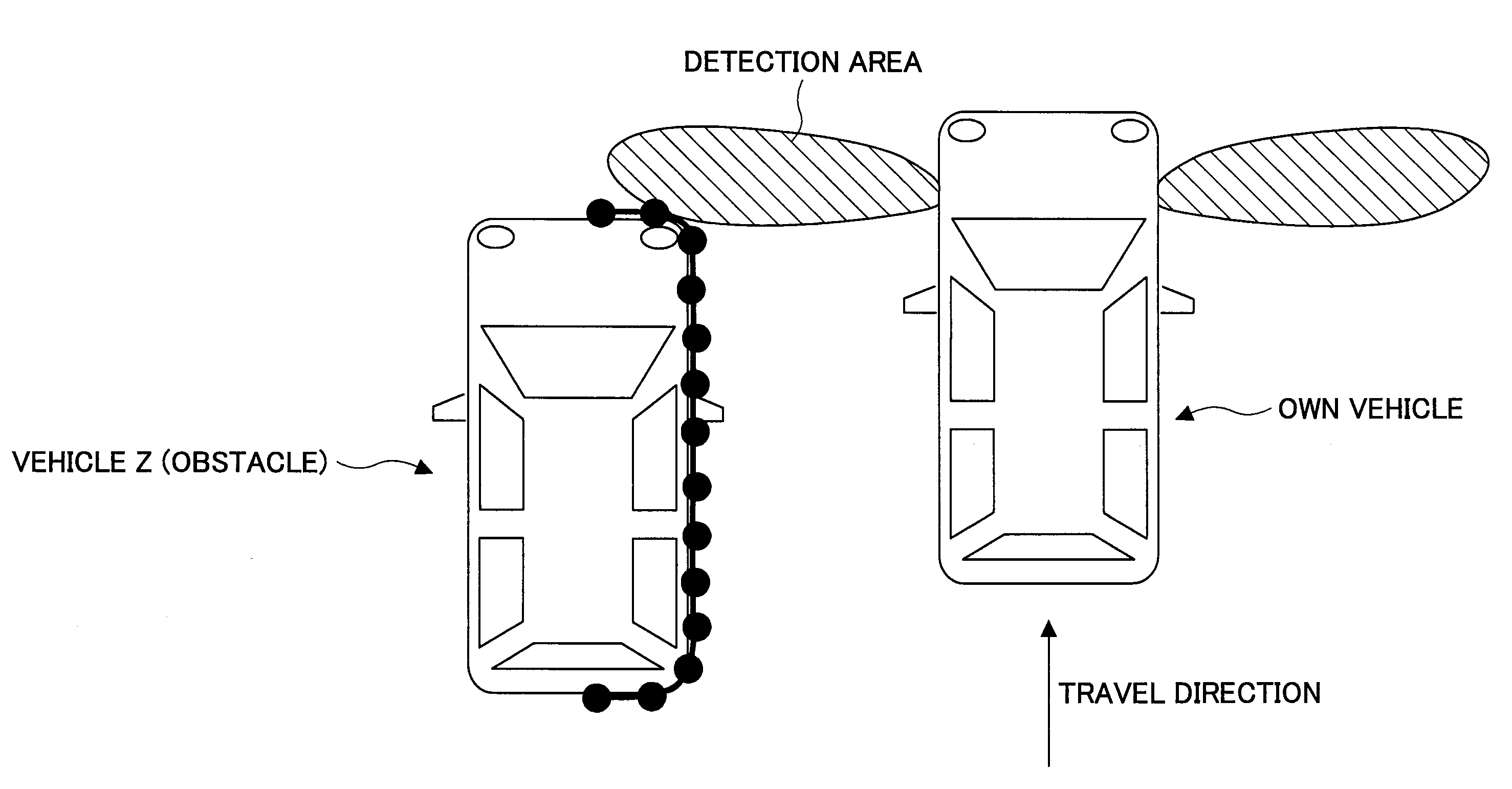
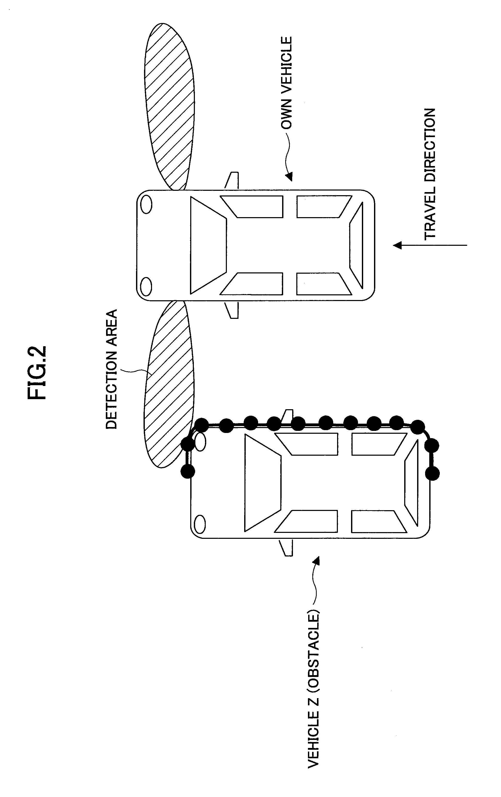
In this connection, according to the parking assisting apparatus of JP2003-54341 A, since the target parking position is determined only based on the relationship between the vehicle and the obstacle adjacent to the parking space, the problem is that the target parking position which is biased with respect to the parking section line is determined if another vehicle which is detected as an obstacle is parked in a biased manner with respect to the neighboring parking section line, for example.
Although the parking section line can be detected by image recognition or the like using a camera, there may be a situation where the parking section line cannot be detected due to influence of insufficient light at night, insufficient coverage of the camera, snow cover, etc., or the fact that no parking section line is painted in the first place.
Furthermore, there is a situation where a target track cannot be generated to guide the vehicle within the parking section line without any bias even in the case where the parking section line can be detected.

Method used


Image

  • Parking assist apparatus and method
  • Parking assist apparatus and method
  • Parking assist apparatus and method

Examples


Embodiment Construction

[0052]In the following, the best mode for carrying out the present invention will be described in detail by referring to the accompanying drawings.

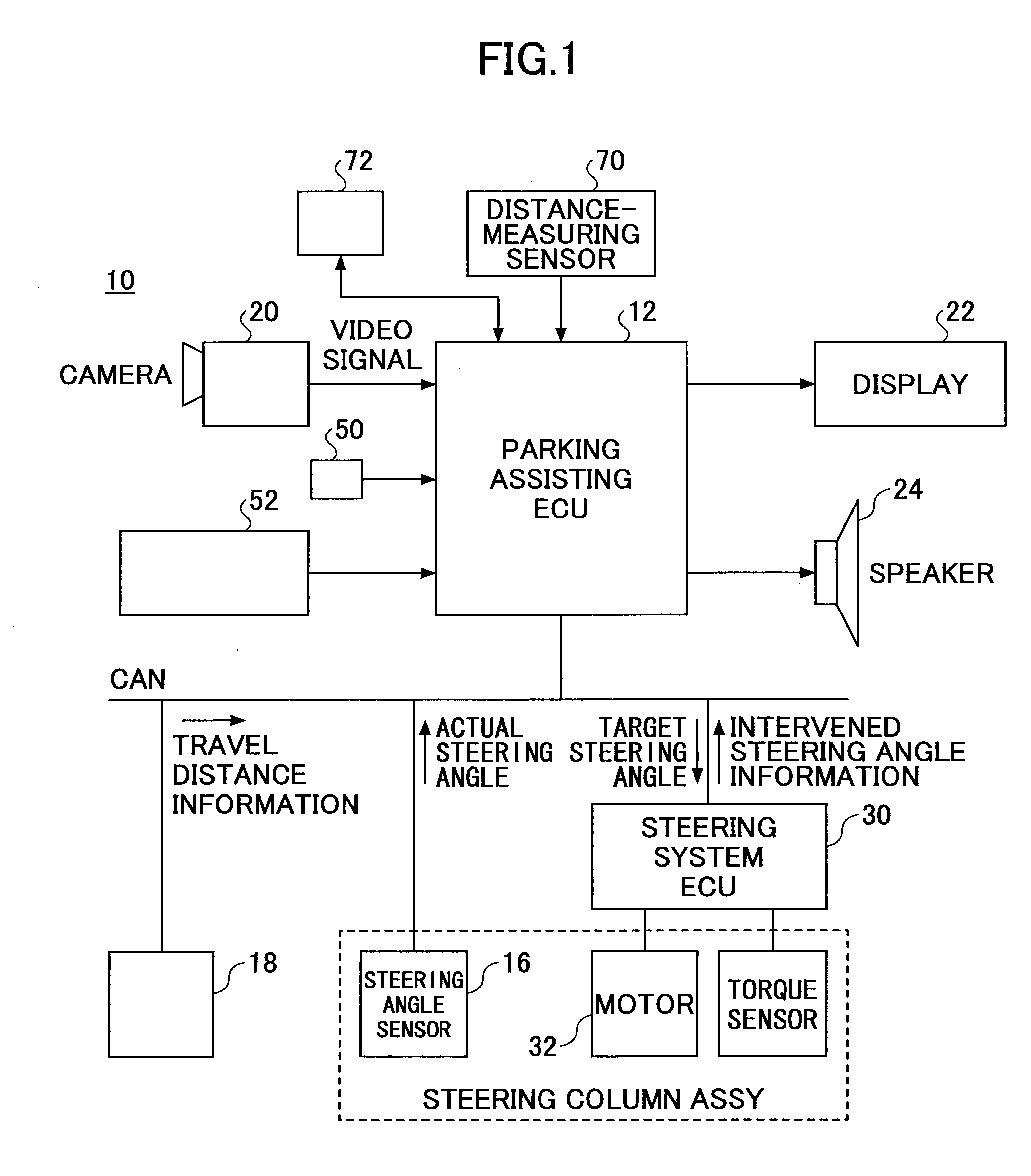
[0053]FIG. 1 is a system diagram of an embodiment of a parking assisting apparatus 10 according to the present invention. As shown in FIG. 1, the parking assisting apparatus 10 is comprised mainly of an electronic control unit 12 (hereafter referred to as a parking assisting ECU 12). The parking assisting ECU 12 is comprised mainly of a microprocessor that includes a CPU, a ROM, a RAM, etc., (not shown) which are interconnected via appropriate buses. In the ROM are stored the computer readable programs to be carried out by the CPU and data.

[0054]The parking assisting ECU 12 is connected to a steering angle sensor 16 for detecting the steering angle of the steering wheel (not shown), and a vehicle speed sensor 18 for detecting the speed of the vehicle, via appropriate buses such as a CAN (Controller Area Network) or a high-speed communicat...


PUM


Abstract

It is an object of the present invention to provide a parking assisting apparatus which can selectively determine an appropriate target parking position, which can be used for parking assisting, with an appropriate priority, by appropriately using obstacle detecting means and parking space detecting means in a coordinated fashion. The present invention is a parking assisting apparatus for assisting parking a vehicle, comprising the obstacle detecting means for detecting an obstacle near the vehicle; and parking section line detecting means for detecting a parking section line painted on the ground; wherein if the parking section line is detected by the parking section line detecting means, the apparatus calculates the target parking position based on the detected parking section line.

Description

TECHNICAL FIELD[0001]The present invention relates to a parking assisting apparatus and method for assisting parking a vehicle.BACKGROUND ART[0002]JP2003-54341 A discloses a parking assisting apparatus comprising obstacle detecting means for detecting an obstacle near the vehicle; a vehicle motion calculating section configured to calculate vehicle position and vehicle orientation in a two-dimensional plane based on steering angle and vehicle speed; and a target parking position determining section configured to detect a parking space based on the vehicle motion calculated by the vehicle motion calculating section and the relative positional relationship with respect to the detected obstacle and determine the target parking position.[0003]By the way, in an actual parking situation, drivers generally park vehicles such that the vehicles are appropriately accommodated within the parking section line, while they look at the parking section line painted on the ground to use it as a targ...

Claims


Application Information

Patent Timeline
IPC IPC(8): B60Q1/48
CPCB60R1/00B60R2300/302B60R2300/305B60R2300/8026G08G1/168B60W50/14B62D15/027B62D15/028G08G1/16B60R2300/806G08G1/165G08G1/166G01S2015/935G01S13/867G01S2013/9314G01S2015/936G01S2013/9324G01S15/86G01S2013/93274G01S2013/9323G01S17/86G01S17/931B60R1/26B60R1/31B60R21/0134G06T7/00G08B21/18B60R2300/30
Inventor ENDO, TOMOHIKOMAKINO, YASUSHIKUBOTA, YUICHIKAWABATA, YUKIKO
Owner TOYOTA JIDOSHA KK
Learn More