Piezoelectric ceramic element and portable device

a technology of ceramic elements and piezoelectric transducers, applied in piezoelectric/electrostrictive transducers, mechanical vibration separation, generators/motors, etc., to achieve the effect of easy manufacturing, high reliability in operation or movement, and thin thickness

Inactive Publication Date: 2006-07-13
LENOVO INNOVATIONS LTD HONG KONG
View PDF9 Cites 26 Cited by
  • Summary
  • Abstract
  • Description
  • Claims
  • Application Information

AI Technical Summary

Benefits of technology

[0018] A first object of the present invention is to provide, in consideration of the problems, a piezo-electric ceramic transducer, having a high reliability in operation and easiness in manufacturing while having features of both downsizing and thinned thickness in the piezo-electric ceramic transducer, and a portable device using the piezo-electric ceramic transducer.
[0021] As described above, the two piezo-electric active layers are placed between the two insulating layers, and the two insulating layers are, respectively, disposed on both surfaces of the piezo-electric ceramic transducer in the thickness direction of the transducer. Therefore, an electrical connection with the electrode layers can be led to only one of the insulating layers. As a result, a lead wire for electrical connection with the outside can be led from only one surface of the piezo-electric ceramic transducer. Accordingly, the downsizing and thinned thickness in the piezo-electric ceramic transducer including the lead wire can be achieved. Further, because the piezo-electric active layers and the insulating layers are made of the same material as one another and are formed integrally with each other by sintering, a joining process based on sticking of the layers on each other is unnecessary. Thereby, a manufacturing process is simplified, and reliability against mechanical breakage of the piezo-electric ceramic transducer is improved.
[0022] Further, because the electrode pad is disposed on only one surface of the piezo-electric ceramic transducer, an object, to which displacement of the piezo-electric ceramic transducer should be transmitted, can be joined to the whole surface opposite to the surface on which the electrode pad of the piezo-electric ceramic transducer is disposed. Accordingly, the displacement of the piezo-electric ceramic transducer is efficiently transmitted to the object. Further, in the piezo-electric ceramic transducer, the layers are integrally formed with one another, and sintering distortion is extremely lowered. Therefore, when the piezo-electric ceramic transducer and the object are joined to each other, mechanical working such as polishing and the like is unnecessary. Therefore, the joining process can be easily performed. In addition, because a surface, to which the object is joined, is an insulating layer, even though the object is made of metal, the piezo-electric ceramic transducer can be joined to the object. Accordingly, an installation position of the piezo-electric ceramic transducer according to the present invention is not limited.
[0024] Further, it is preferred that the piezo-electric ceramic transducer according to the present invention has also an intermediate insulating layer between the two piezo-electric active layers. Thereby, a piezo-electric effect caused by the two piezo-electric active layers is more effectively produced, and the number of lead wires led to the outside can be reduced. Further, as to polarization directions of the two piezo-electric active layers, it is preferred that polarization directions of the two piezo-electric layers closest to each other in relation between one piezo-electric active layer and the other piezo-electric active layer be the same as each other. Thereby, voltage applied in a polarization process and in a driving period of time can be lowered.
[0027] In the present invention, the piezo-electric ceramic transducer having high reliability in operation or movement and easily manufactured, while having features of downsizing and thinned thickness in the piezo-electric ceramic transducer, can be obtained. As a result, the piezo-electric ceramic transducer according to the present invention can be installed in a narrow space. Further, because reliability in movement is high, the piezo-electric ceramic transducer can be preferably used as a driving source of a part of the portable device accompanied by mechanical displacement.
[0028] Further, a fundamental resonance frequency can be adjusted by directly joining the elastic body to the piezo-electric ceramic transducer or joining the elastic body through the stationary part to the piezo-electric ceramic transducer. Therefore, the present invention can be also used appropriately as an acoustic device. Particularly, when the stationary part is disposed, a band of the vibration frequency can be widened by placing the stationary part at a position different from a position of the center of the piezo-electric ceramic transducer. Further, when the elastic body is formed into a box and the piezo-electric ceramic transducer is joined to the inside of the box, the piezo-electric ceramic transducer can acts as a non-directivity acoustic device performing acoustic radiation from the whole box.

Problems solved by technology

Further, because the piezo-electric active layers and the insulating layers are made of the same material as one another and are formed integrally with each other by sintering, a joining process based on sticking of the layers on each other is unnecessary.

Method used


Image

  • Piezoelectric ceramic element and portable device
  • Piezoelectric ceramic element and portable device
  • Piezoelectric ceramic element and portable device

Examples


first embodiment

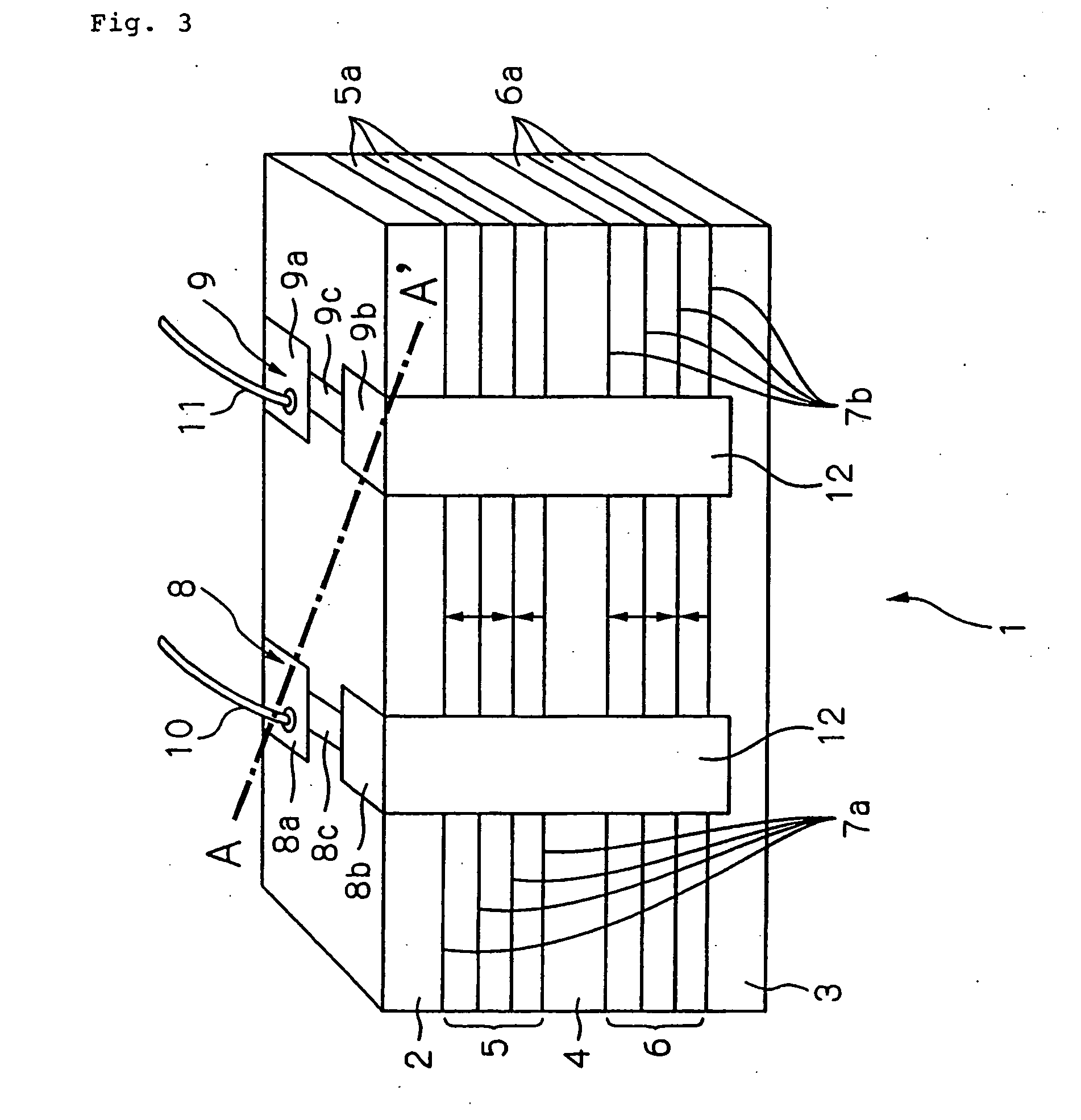
[0050] Referring to FIG. 3, a schematic view of piezo-electric ceramic transducer 1 according to a first embodiment of the present invention is shown.

[0051] Piezo-electric ceramic transducer 1 shown in FIG. 3 is a bimorph type bendable device having two piezo-electric active layers composed of upper piezo-electric active layer 5 and lower piezo-electric active layer 6 and is bent and displaced in a thickness direction of piezo-electric ceramic transducer 1 when a voltage is applied to piezo-electric ceramic transducer 1 through electrode pads 8 and 9. When the applied voltage is a direct current voltage, piezo-electric ceramic transducer 1 is displaced towards one direction. When the applied voltage is an alternating current voltage, piezo-electric ceramic transducer 1 is vibrated. The vibration is periodical repetition of bends and displacements in opposite directions. Therefore, in following descriptions, when the vibration is not particularly distinguished from the displacement,...

second embodiment

[0083] Referring to FIG. 8, a perspective view of an acoustic device using a piezo-electric ceramic transducer according to a second embodiment of the present invention is shown.

[0084] In the present embodiment, stationary part 36 is attached to piezo-electric ceramic transducer 21, and stationary part 36 is fixed to elastic body 35. Because piezo-electric ceramic transducer 21 is the same as that described in the first embodiment, detailed description of piezo-electric ceramic transducer 21 is omitted. Stationary part 36 changes a displacement behavior of piezo-electric ceramic transducer 21, and material of stationary part 36 is not particularly restricted on condition that the material can be joined to piezo-electric ceramic transducer 21. Resin, metal, ceramics material and the like can be used as material of stationary part 36.

[0085] Material, shape and the like of elastic body 35 are selected such that a displacement of piezo-electric ceramic transducer 21 in a thickness dir...

##ventive example 1

INVENTIVE EXAMPLE 1

[0097] In Inventive Example 1, piezo-electric ceramic transducer 51 shown in FIG. 12 was manufactured. The configuration of layers of piezo-electric ceramic transducer 51 shown in FIG. 12 is shown in FIG. 13.

[0098] In this Example, fifty piezo-electric ceramic transducers 51 were manufactured. Green sheet method used for manufacturing a ceramic condenser or the like was applied to manufacturing of each piezo-electric ceramic transducer 51. Outside dimensions of piezo-electric ceramic transducer 51 were set to be 35 mm in length, 5 mm in width and 0.532 mm in thickness. Further, the configuration of layers of piezo-electric ceramic transducer 51 was set so as to have upper insulating layer 52, upper piezo-electric active layer 55 composed of a single piezo-electric layer, upper electrode layers 57a disposed on both surfaces of upper piezo-electric active layer 55 in a thickness direction thereof, intermediate insulating layer 54, lower piezo-electric active layer ...


PUM


Abstract

Piezo-electric ceramic transducer 1 has upper piezo-electric active layer 5 and lower piezo-electric active layer 6. Upper insulating layer 2 and lower insulating layer 3, between which upper piezo-electric active layer 5 and lower piezo-electric active layer 6 are placed, are disposed on both surfaces of piezo-electric ceramic transducer 1 in a thickness direction thereof. Two electrode pads 8 and 9 are disposed on a surface of upper insulating layer 2. Electrode pads 8 and 9 are connected with upper electrode layers 7a and lower electrode layers 7b via connection members 12, and voltages are applied to upper piezo-electric active layer 5 and lower piezo-electric active layer 6 via electrode pads 8 and 9. Insulating layers 2, 3 and 4 and piezo-electric active layers 5 and 6 are made of the same material as one another and are integrated by sintering.

Description

TECHNICAL FIELD [0001] The present invention relates to a piezo-electric ceramic transducer which is warped and deformed due to a piezo-electric traverse effect, and a portable device using the piezo-electric ceramic transducer. BACKGROUND ART [0002] Recently, portable devices such as a portable telephone, a notebook-sized personal computer, a personal digital assistant (PDA) and the like have been frequently used. These portable devices have been served for various purposes of use with the development of network system and software, and convenience for users have been heightened. Hereby, types of functional components on-boarded in portable devices such as a speaker, a microphone, a receiver, a vibrator, a camera, a liquid crystal display, a card memory, LSI, an infrared ray communication module and the like tend to increase in number. [0003] To heighten portability and convenience of portable devices, downsizing and thinned thickness of them have been required. However, increase o...

Claims


Application Information

Patent Timeline
Patent Type & Authority Applications(United States)
IPC IPC(8): H01L41/083B06B1/06H01L41/09H01L41/187H01L41/257H04R1/00H04R1/02H04R17/00
CPCB06B1/0603H01L41/083H01L41/0472H01L41/094H10N30/872H10N30/2042H10N30/50
Inventor SASAKI, YASUHIRO
Owner LENOVO INNOVATIONS LTD HONG KONG
Why Eureka
Try Eureka