Obstacle detection system notably for an anticollision system

a detection system and anticollision technology, applied in the direction of measuring devices, using reradiation, instruments, etc., can solve the problems of difficult pilots to see the wings and engines of aircraft, increasing the frequency of aircraft collisions with various obstacles on the ground, and reducing the cost of aircraft integration, so as to reduce the cost and detect obstacles on the ground very quickly

Active Publication Date: 2009-07-09
BEIJING VOYAGER TECH CO LTD
View PDF17 Cites 44 Cited by
  • Summary
  • Abstract
  • Description
  • Claims
  • Application Information

AI Technical Summary

Benefits of technology

[0025]The main advantages of the device according to the invention are notably that it is easy to integrate onboard an aircraft a

Problems solved by technology

Collisions between aircraft and various obstacles on the ground are ever more frequent, notably when an aircraft attains a parking position from an airport landing runway.
For example, on a wide-bodied aircraft, it is hard for the pilot of the aircraft to see the wings and engines.
This type of incident, in addition to the costs of repairing the aircraft, gives rise to the grounding of the aircraft.
This grounding of the aircraft is financially prejudicial to the company owning this aircraft.
However, the density of the traffic on the airports is such that these means are insufficient to ensure the final guidance of aircraft towards their parking position.
Moreover these means are often ineffective in foggy weather for example and generally when the meteorological conditions are bad or at nightfall.
Cameras are, however, ineffective with poor meteorological conditions.
Moreover, devices based on cameras do not provide the pilot with accurate information either on the distance between the aircraft and a potential obstacle, or on the relative speed of the aircraft with respect to the obstacle.
Cameras thus

Method used


Image

  • Obstacle detection system notably for an anticollision system
  • Obstacle detection system notably for an anticollision system
  • Obstacle detection system notably for an anticollision system

Examples


Embodiment Construction

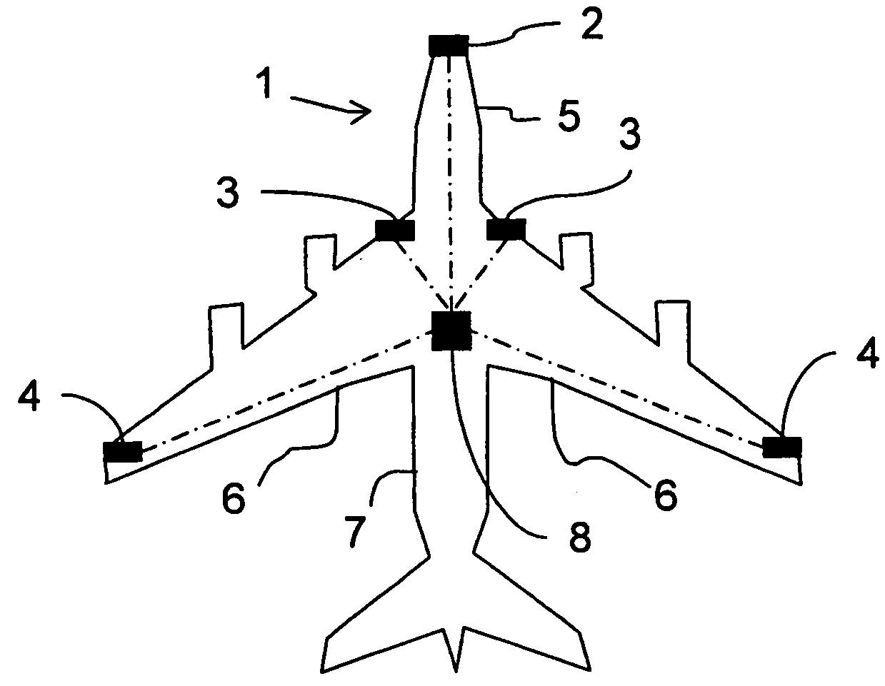
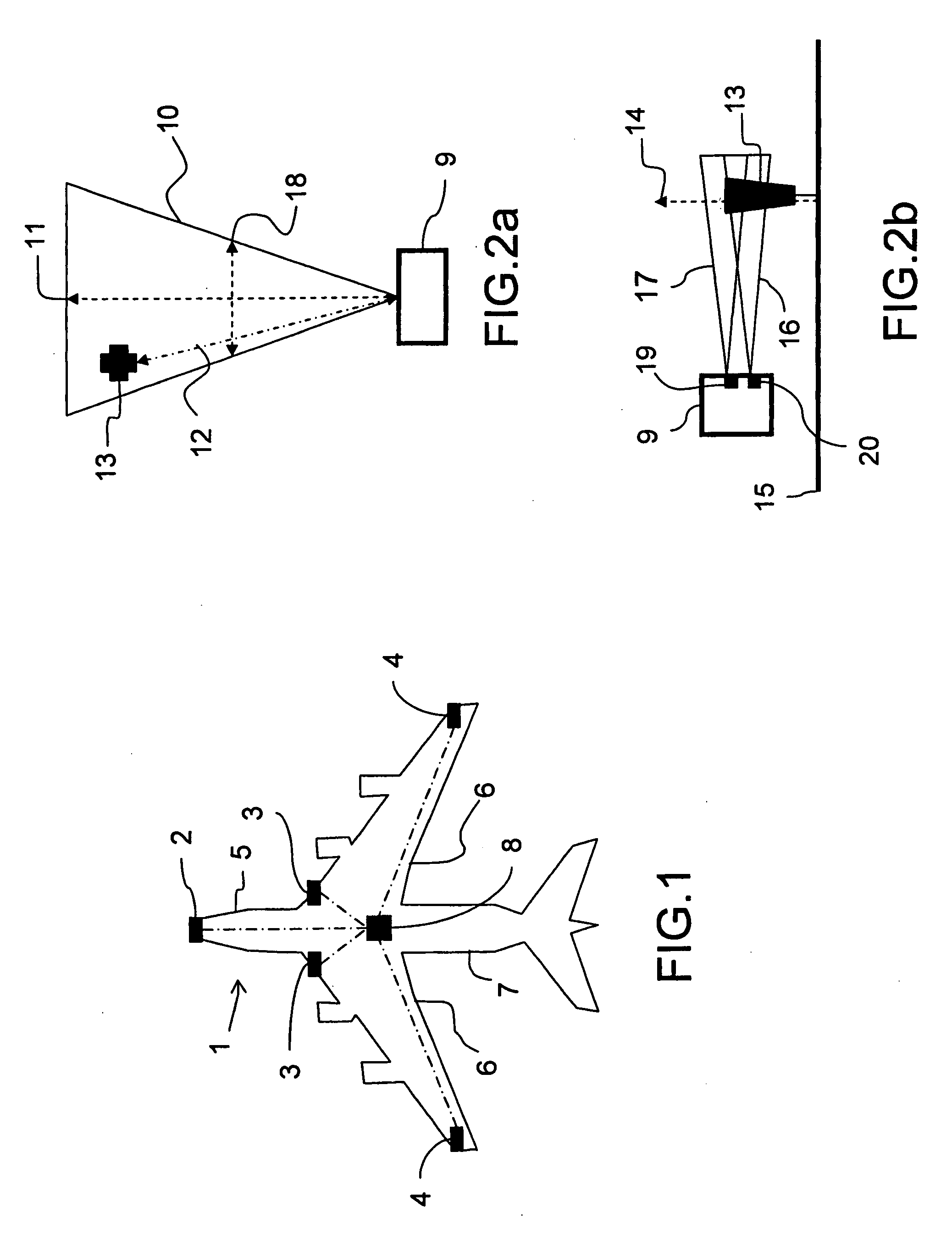
[0036]FIG. 1 represents an aircraft 1 equipped with sensors 2, 3, 4 according to the invention. The sensors 2, 3, 4 are continuous millimetric wave radars. The continuous waves allow the radars 2, 3, 4 to emit and to receive simultaneously. This makes it possible to have no blind zone during detection. The radars 2, 3, 4 emit for example at a frequency of the order of 70 GHz. The radars 2, 3, 4 form a sensor array. The radars 2, 3, 4 are additionally linked to a detection data processing system 8. Thanks to the detection data originating from the various radars 2, 3, 4, the data processing system 8 can produce a synthetic and dynamic image of the environment of the aircraft 1. This synthetic image is an overall view of the situation in the environs of sensitive parts of the aircraft 1 such as the wings 6. This view can comprise fixed obstacles and also obstacles possessing a low speed of movement. The synthetic image is thereafter presented to the pilot of the aircraft 1 so that he ...


PUM


Abstract

The present invention relates to system for detecting obstacles (13, 55, 56, 57) on the ground (15) onboard a carrier (1). The detection system comprises at least two continuous-wave radars (2, 3, 4). The radars (2, 3, 4) are linked to a system (15) for utilizing the detection data arising from the radars (2, 3, 4). The detection system performs localization of an obstacle (13, 55, 56, 57): along a radial axis (12) between a radar (2, 3, 4) and the obstacle (13, 55, 56, 57), by calculating the distance between the radar (2, 3, 4) and the obstacle (13, 55, 56, 57); along a vertical axis (14) with respect to a radar (2, 3, 4), by calculating the elevation of the obstacle (13, 55, 56, 57) using monopulse deviation-measurement processing; The detection system performs localization of an obstacles along a horizontal axis (18) transverse with respect to a sighting axis (11) of a radar (2, 3, 4), by calculating the azimuthal position of the obstacle (13, 55, 56, 57). The invention applies notably in respect of the detection of obstacles on the ground so as to avoid any collision between a taxiing aircraft and these obstacles.

Description

RELATED APPLICATIONS[0001]The present application is based on, and claims priority from, French Application Number 07 01927, filed Mar. 16, 2007, the disclosure of which is hereby incorporated by reference herein in its entirety.FIELD OF THE INVENTION[0002]The present invention relates to an obstacle detection system for an anticollision system notably for a taxiing aircraft. The invention applies notably in respect of the detection of obstacles on the ground in order to avoid any collision between a taxiing aircraft and these obstacles.BACKGROUND OF THE INVENTION[0003]The density of airport traffic is ever greater both in the air and on the ground. Collisions between aircraft and various obstacles on the ground are ever more frequent, notably when an aircraft attains a parking position from an airport landing runway. For example, on a wide-bodied aircraft, it is hard for the pilot of the aircraft to see the wings and engines. The wings and engines are therefore particularly exposed...

Claims


Application Information

Patent Timeline
IPC IPC(8): G01S13/93G01S13/00G01S13/933
CPCG01S13/44G01S13/9303G01S13/584G01S13/933
Inventor CORNIC, PASCALLE BIHAN, PATRICKAUDIC, YVESLACOMME, PHILIPPE
Owner BEIJING VOYAGER TECH CO LTD
Why Eureka
Try Eureka