Image display

a flat panel display and large-scale technology, applied in the field of large-scale flat-panel displays, can solve the problems of increasing the flow rate of the fan and inhibiting achieve the effect of increasing the noise of the fan, effective cooling, and not increasing the fan nois

Inactive Publication Date: 2009-07-09
MAXELL HLDG LTD
View PDF4 Cites 57 Cited by
  • Summary
  • Abstract
  • Description
  • Claims
  • Application Information

AI Technical Summary

Benefits of technology

[0007]A cooling structure for image displays has been required which effectively cools the display panel module, the various boards, and the image processing electronic components installed at the upper end of the display panel module without increasing the fan noise.
[0008]An object of the present invention is to provide a reliable, high-brightness and high-definition image display which solves the above-described problems with the conventional techniques to promote the cooling of the upper, hot portion of the display panel module, the various boards, and the image processing electronic components at the upper end of the display panel module while inhibiting a possible increase in fan noise.
[0009]To accomplish the object, the present invention provides an image display comprising a flat display panel module, a display-surface-side cover installed on a display surface side of the display panel module, a non-display-surface-side cover installed on a non-display surface side of the display panel module, a display driving board, a power supply board, and a cooling fan, wherein a case of the cooling fan is larger than a distance between the display panel module and the non-display-surface-side cover in an area in which the cooling fan is installed, and a first end of the case of the cooling fan which is closer to the non-display-surface-side cover is positioned above a second end of the case which is closer to the display panel module (the cooling fan is located at an angle of 30° to 60° to a horizontal plane) The present invention is unlikely to be restricted by the depth dimension of a housing, thus enabling a fan with a larger diameter to be mounted in the thin housing. As a result, the flow rate of the fan can be increased with a possible increase in noise inhibited. Moreover, a relatively cool flow, which is likely to rise from the lower side of the housing along the non-display-surface-side cover, can be allowed to flow like a jet directly to the upper side of the display panel module, which is in the greatest need for promotion of cooling, and image processing electronic components installed at the upper end of the display panel. Consequently, the cooling can be promoted, providing a reliable, high-brightness and high-definition image display.

Problems solved by technology

As a result, the flow rate of the fan can be increased with a possible increase in noise inhibited.

Method used


Image

  • Image display
  • Image display
  • Image display

Examples


second embodiment

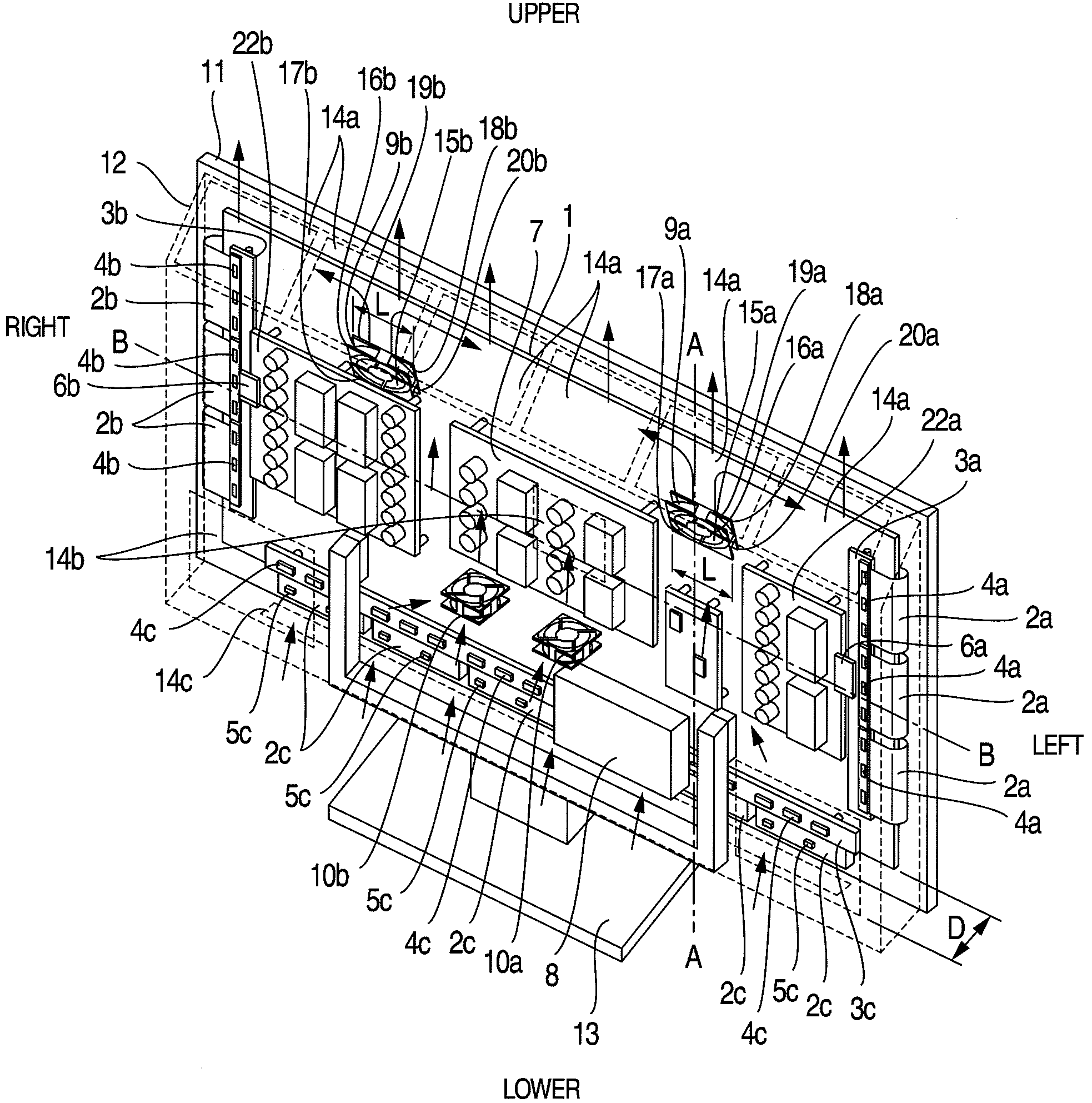
[0038]In the present invention, the installation position of the cooling fan 9 is such that in the vertical direction, the cooling fan 9 is installed above the center of the display panel module 1, corresponding to line B-B in FIG. 6, and in the lateral direction, at least one cooling fan 9 is installed between the display driving board 22 and the power supply board 7, as shown in FIG. 6.

[0039]In a large-sized image display, there is a long distance between the display driving board 22 and the power supply board 7. Thus, the cooling fan 9 can be installed between the display driving board 22 and the power supply board 7. The display driving board 22 and the power supply board 7 are heat generating components. Thus, the air temperature is likely to increase in the vicinity of these boards. On the other hand, when the cooling fan 9 is actuated, a flow of air flows into the housing though the openings 14b and 14c and the like located on the lower side of the non-display-surface-side co...

embodiment 1

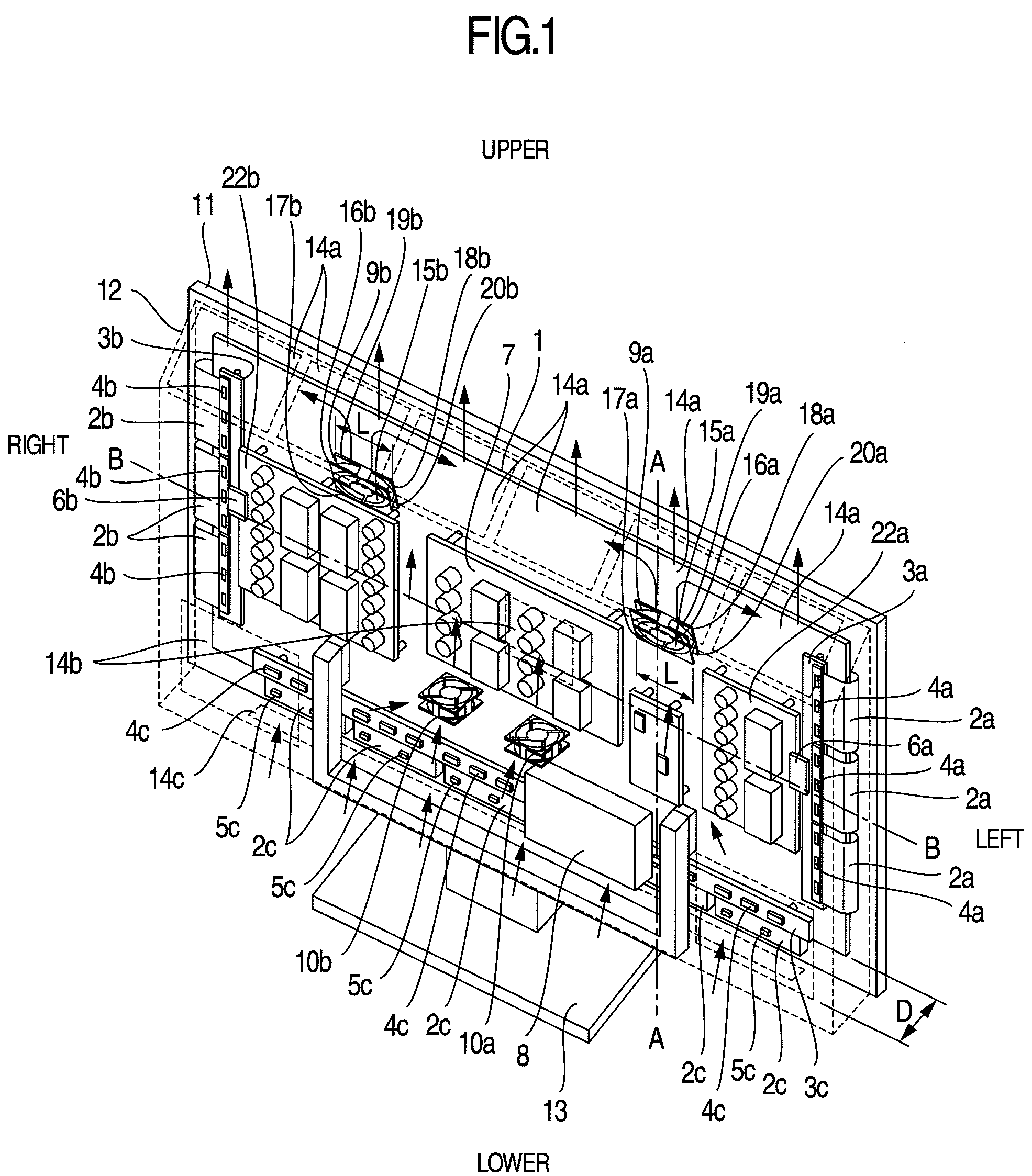
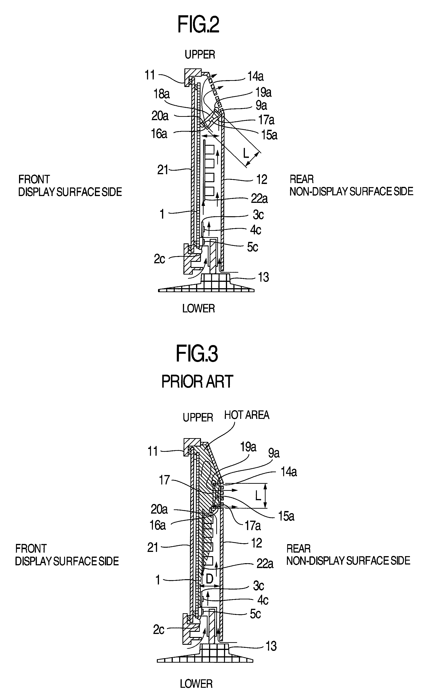
[0051]In the non-display-surface-side cover 12, in particular, the rear opening 14b is preferably not formed in the vicinity of the rear side of the inlet 17 of the cooling fan 9 as shown in FIG. 5 for If the opening 14b is present in the non-display-surface-side cover 12 in the vicinity of the rear side of the inlet 17 of the cooling fan 9, the cooling fan 9 sucks air intensively through the opening 14b. Consequently, dust in the air is likely to be built up in the opening 14b portion during a prolonged operation. When sucked into the housing by the cooling fan 9, the built-up dust disperses to the terminal portion in the housing. Then, a new risk of a defect such as an electric short circuit may occur. Moreover, if the opening 14b is present in the non-display-surface-side cover 12 in the vicinity of the rear side of the inlet 17 of the cooling fan 9, noise emitted through the opening 14b by the cooling fan 9 disadvantageously leaks readily to the exterior of the housing. Thus, b...


PUM


Abstract

To provide a reliable high brightness and definition image display by inhibiting a possible increase in fan noise and promoting cooling of an upper, hot portion of a display panel module, various boards, and image processing electronic components, an image display includes a flat display panel module, a display surface side cover on a display surface side of the display panel module, a non display surface side cover on a non display surface side of the display panel module, a display driving board, a power supply board, and a cooling fan, wherein a case of the cooling fan is larger than a distance between the display panel module and the non display surface side cover in an area where the cooling fan is installed, and a first end of the case of the cooling fan closer to the non display surface-side cover is positioned above a second end of the case closer to the display panel module.

Description

BACKGROUND OF THE INVENTION[0001]The present invention relates to a large-sized flat panel display, and is preferably applied particularly to a plasma display or the like which needs to efficiently radiate heat from a display panel, various boards, and image processing electronic components.[0002]Large-sized flat panel displays such as plasma displays providing high-brightness and high-definition images have been required. This has led to an increase in the number of image processing electronic components and in the quantity of heat generated by a display panel and various boards. Thus, a challenge for the large-sized flat panel display is to cool these heat generating components. As is well-known, to cope with the increase in the quantity of heat generated by the display panel and the various boards, an exhausting cooling fan is obliquely installed on a ceiling portion of a rear cover to discharge exhaust heat from the display panel module and various boards for cooling. This confi...

Claims


Application Information

Patent Timeline
Patent Type & Authority Applications(United States)
IPC IPC(8): G09G3/20
CPCH05K7/20972
Inventor ISOSHIMA, NOBUYUKIMIYOSHI, KOHEIRI, MIKASEKIGUCHI, SEIICHIYAMADA, YUTAKA
Owner MAXELL HLDG LTD
Why Eureka
Try Eureka