Load Driving and Diagnosis System and Control Method

Active Publication Date: 2009-07-09
HITACHI ASTEMO LTD
View PDF3 Cites 4 Cited by
  • Summary
  • Abstract
  • Description
  • Claims
  • Application Information

AI Technical Summary

Benefits of technology

[0038]According to the present invention, a load driving and diagnosis system that even when a break occurs in an overcurrent condition, can normally execute breaking irrespective of the state of a terminal capacitor or a parasitic inductor of an external harness can be realized.
[0039]Moreover, a load driving and diagnosis system that even when a break derived from an overcurrent persists, accurately grasps the state and performs optimal diagnosis can be realized.

Problems solved by technology

However, when the semiconductor switching circuit 13 is broken, if the negative current like the one 16b flows, the constitution including the semiconductor integrated circuit 31 may be gravely damaged.
Consequently, another parasitic element may be generated and a malfunction of a circuit maybe invited.
Eventually, the semiconductor integrated circuit may be thermally destroyed or any other serious problem may arise.
However, the durability against an externally applied surge may be degraded, and surge destruction may occur.
Moreover, even when an optimal capacitance is selected for the terminal capacitor for fear an LC oscillation may occur, since the requirement for the parasitic inductor 41 varies depending on the length of the external harness 40 or the like, it is very hard to determine the capacitance of the terminal capacitor which meets every requirement.
If a large current keeps flowing for a long period of time, the semiconductor switching circuit would be destroyed due to heat dissipation.
In other words, there is difficulty in selecting an optimal gradient in a breaking current, which brings about neither the surge 29a nor thermal destruction, and realizing a circuit that employs the breaking current.
Moreover, a control-related problem described below confronts actions to be performed during a break derived from generation of an overcurrent.
Therefore, a trouble may arise in terms of control.

Method used


Image

  • Load Driving and Diagnosis System and Control Method
  • Load Driving and Diagnosis System and Control Method
  • Load Driving and Diagnosis System and Control Method

Examples


first embodiment

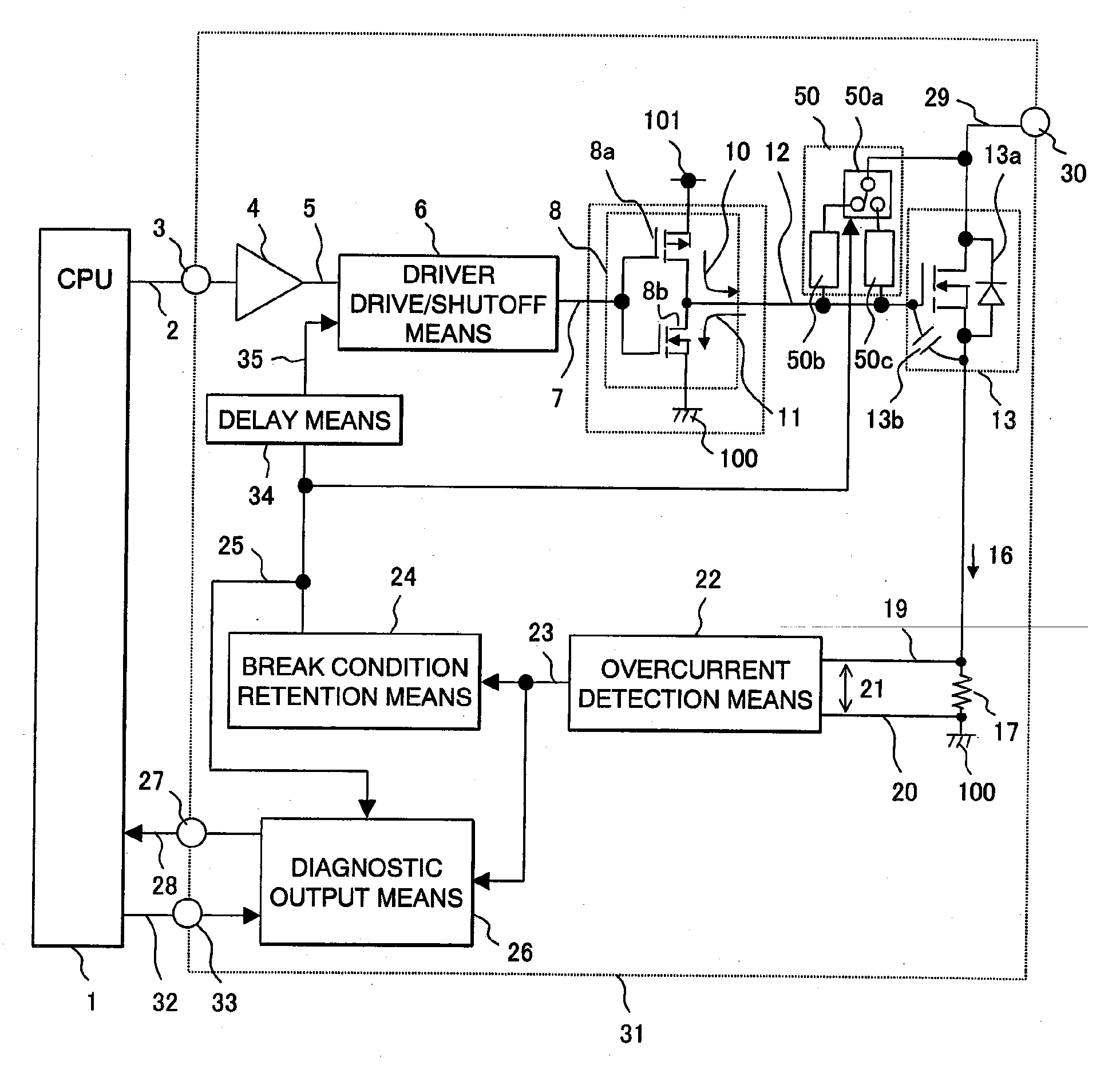
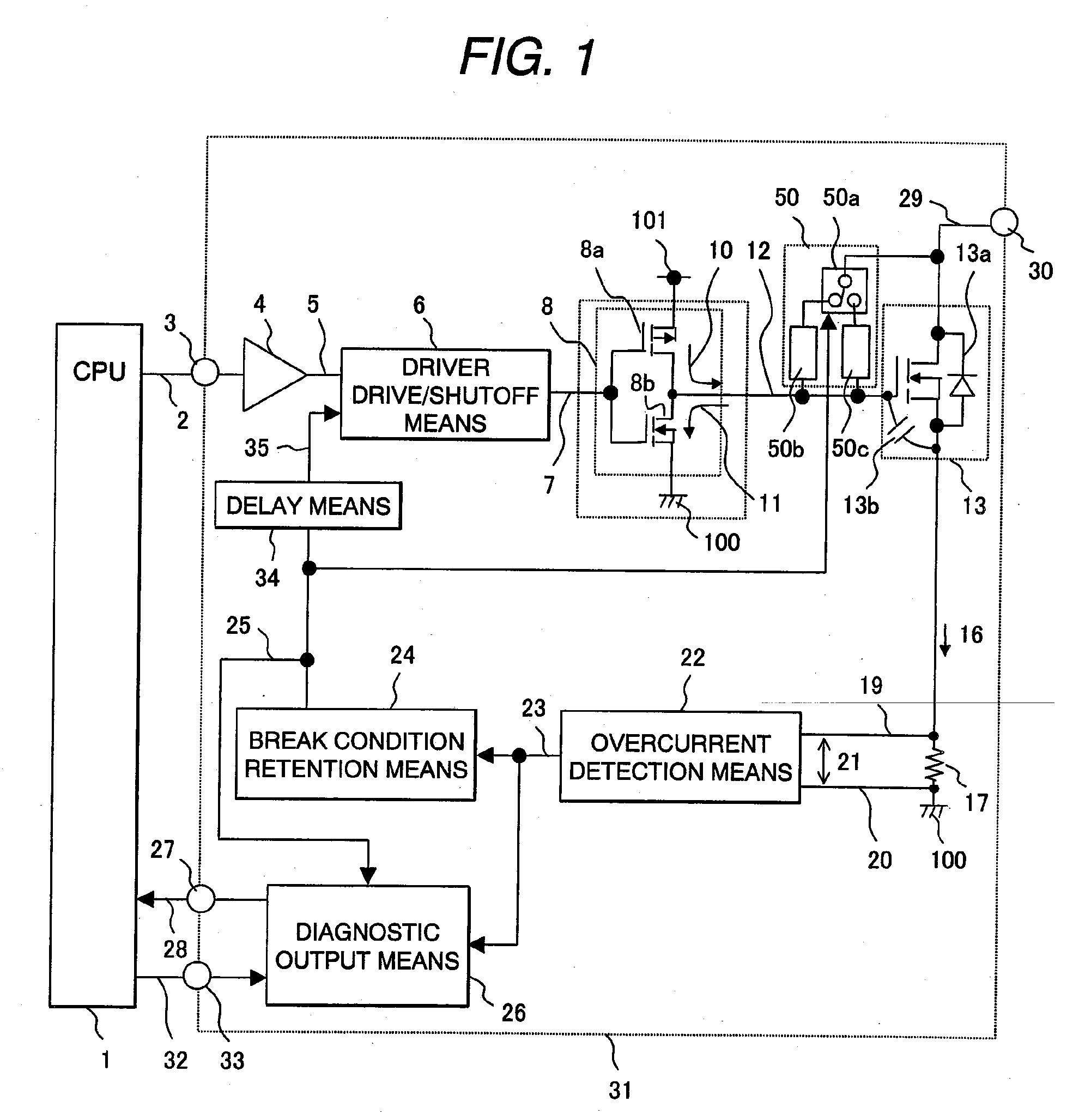
[0060]FIG. 1 is a block diagram showing an example of a load driving and diagnosis system for the purpose of explaining the first embodiment in accordance with the present invention. In FIG. 1, there are shown a CPU control means 1 that controls the timing of energizing or de-energizing a load, a load drive command 2, an input command terminal 3 of an integrated circuit 31, an input buffer 4, an internal command signal 5, a driver drive / shutoff means 6 that drives or shuts off a driver, a drive / shutoff control signal 7, a driver means 8 that drives a semiconductor switch, a high-side driver 8a, a low-side driver 8b, a gate driving sink current 10 produced by the high-side driver 8a, and a gate driving source current 11 produced by the low-side driver 8b.

[0061]Reference numeral 12 is a gate signal with which the semiconductor switch is directly controlled. Reference numeral 13 is a semiconductor switching circuit that is the semiconductor switch. Reference numeral 13a is a parasitic...

second embodiment

[0083]Next, the second embodiment of the present invention will be described in conjunction with FIG. 5. FIG. 5 is a block diagram showing an example of a load driving and diagnosis system. In FIG. 5, the pieces of output voltage holding means 50d and 50e included in the voltage holding means 50 are grounded. When the switching circuit output voltage 29 surges, if the output voltage has to be held at a predetermined value, a value A holding current 50f or a value B holding current 50g flows during an action of voltage holding. The other constituent features are identical to those of the first embodiment.

[0084]The actions to be performed in the present embodiment shown in FIG. 5 will be described in conjunction with the timing chart of FIG. 6. In FIG. 6, when the load drive command 2 with which the semiconductor switching circuit 13 is turned off is inputted at timing B in the same manner as it is in the first embodiment, since the contacts of the selection switch 50a of the voltage ...

third embodiment

[0087]Next, the third embodiment of the present invention will be described in conjunction with FIG. 7. FIG. 7 is a block diagram showing an example of a load driving and diagnosis system. In FIG. 7, there is shown a diagnostic output means 26 that outputs a result of diagnosis to outside, for example, to the CPU control means 1, and that inputs the overcurrent detection signal 23 sent from the overcurrent detection means 22, the overcurrent break holding signal 25 sent from the break condition holding means 24, and the gate signal 12.

[0088]In this constitution, the diagnostic output means outputs the CPU readout diagnosis signal 28 on the basis of the CPU readout control signal 32 sent from the CPU control means 1.

[0089]FIG. 8 is an explanatory diagram for use in explaining the internal constitution of the diagnostic output means 26. In FIG. 8, there are shown an output circuit 26a that outputs the CPU readout diagnosis signal 28 on the basis of the CPU readout control signal 32, a...


PUM


Abstract

A load driving and diagnosis system controls the feed and block of a load current flowing into an inductor such as a solenoid. The load driving and diagnosis system holds a counter-electromotive force, which is developed when the load current is blocked, at a voltage higher than a supply voltage so that the load current will decay for a short time. When an overcurrent condition is established in the load driving and diagnosis system because of a short circuit to a power supply, a malfunction of a circuit or destruction thereof may take place. In addition to a voltage holding means that holds a switching circuit output voltage at a predetermined voltage, a voltage holding means having a different predetermined voltage set therein is included. Moreover, a selection switch that switches the predetermined voltages according to a detected overcurrent condition is included.

Description

CLAIM OF PRIORITY[0001]The present application claims priority from Japanese patent application serial No. 2008-002134 filed on Jan. 9, 2008, the content of which is hereby incorporated by reference into this applicationBACKGROUND OF THE INVENTION[0002]1. Field of the Invention[0003]The present invention relates to protection of a load driving and diagnosis system that feeds a current to a connected load so as to drive the load, and a diagnosis method implemented in the system.[0004]2. Description of the Related Art[0005]Many loads are mounted in a vehicle, and switches formed with semiconductors are used to control conductions of the loads. The semiconductor switches are generally adopted because they contribute to a reduction in a price or a weight. For a further reduction in the price, a control device having a semiconductor switch and a drive circuit, which drives the semiconductor switch, integrated thereinto is often employed in the form of an integrated circuit. Referring to ...

Claims


Application Information

Patent Timeline
IPC IPC(8): H02H3/093H02H3/08
CPCH03K17/18H03K17/0822
Inventor WATANABE, MITSUHIKOSATO, CHIHIROOURA, RYOICHIKURIMOTO, HIROFUMIONO, KOICHI
Owner HITACHI ASTEMO LTD
Why Eureka
Try Eureka