Diaphragm and Electrical-Acoustic Transducer having the same

Inactive Publication Date: 2009-07-09
MERRY ELECTRONICS CO LTD
View PDF10 Cites 0 Cited by
  • Summary
  • Abstract
  • Description
  • Claims
  • Application Information

AI Technical Summary

Benefits of technology

[0008]Accordingly, it is an object of the present invention to provide a diaphragm that takes less manufacturing proce

Problems solved by technology

Hence, the manufacturing of the diaphragm must involve rather complicated procedures of material preparatio

Method used


Image

  • Diaphragm and Electrical-Acoustic Transducer having the same
  • Diaphragm and Electrical-Acoustic Transducer having the same
  • Diaphragm and Electrical-Acoustic Transducer having the same

Examples


Embodiment Construction

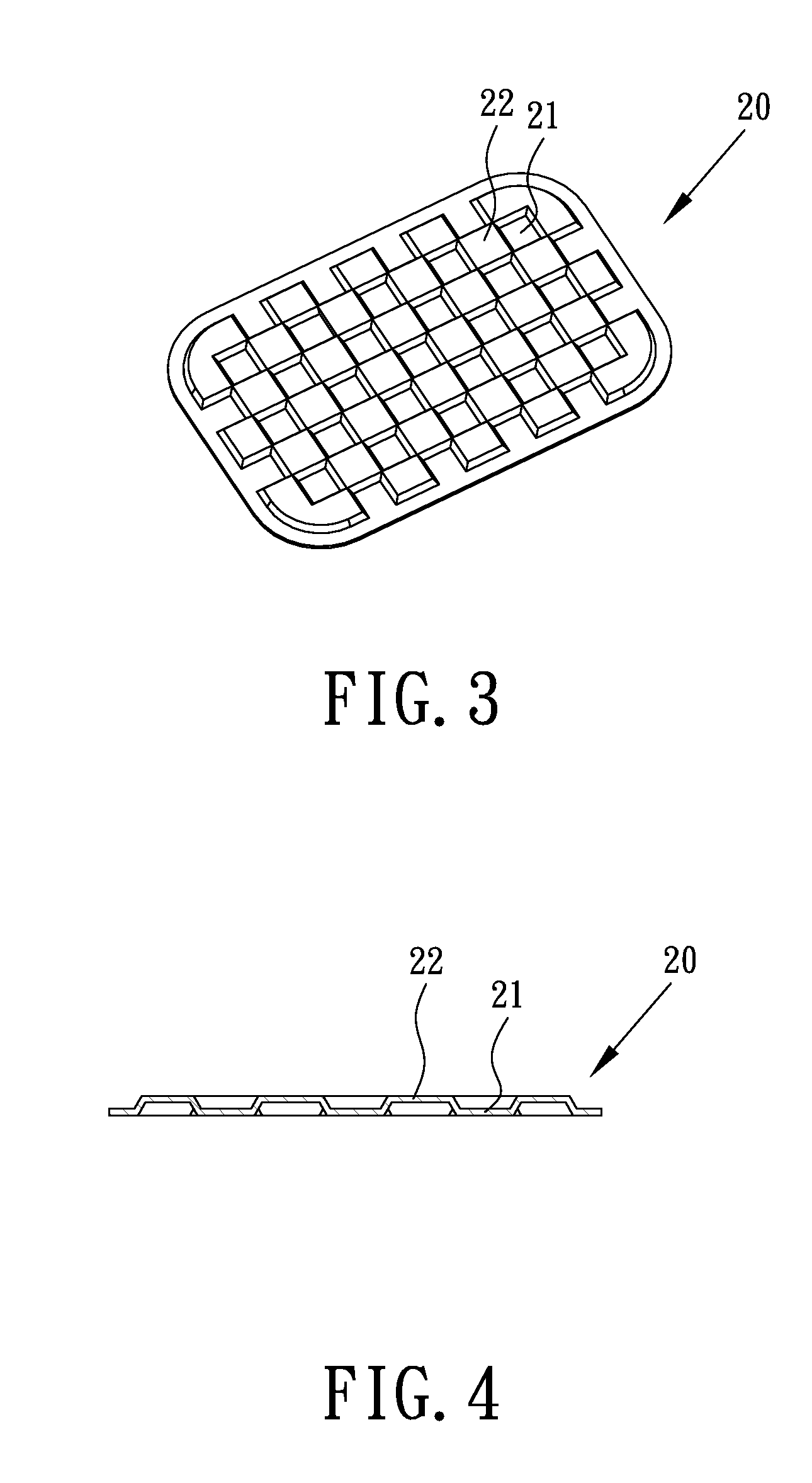
[0019]Referring to FIG. 3 and FIG. 4, a diaphragm 20 according to a preferred embodiment of the present invention is shown. The diaphragm 20 is made of metal. Preferably, the diaphragm 20 is made of aluminum. The reason for choosing is because aluminum is easy to be formed into a thin and light layer. In addition, aluminum has a desirable appearance and yet is cost effective. Further, the aluminum is capable of generating acoustic waves of superior audio quality. It is understood however that the material of the diaphragm is not limited to aluminum.

[0020]As shown in FIG. 3, the diaphragm has an essentially squared shape, on which there is a pattern including multiple concave parts 21 and multiple convex parts 22. The concave parts 21 and the convex parts 22 cross each other in a matrix arrangement, that is, each concave part 21 is surrounded by four convex parts 22 respectively, and each convex part 22 is surrounded by four concave parts 21 respectively. As shown in FIG. 4, the cros...


PUM


Abstract

An electrical-acoustic transducer includes a housing, a magnetic circuit device, a voice coil and a diaphragm. The magnetic circuit device is disposed in the housing and generates a magnetic circuit. The voice coil is disposed on the path of the magnetic circuit, and configured for generating magnetism upon receiving an electrical power. The diaphragm is made of metal, fixedly combined with the voice coil and having a scraggy cross section. When the voice coil of the electrical-acoustic transducer generates the magnetism according to the electrical power and interacts with the magnetic circuit, the diaphragm vibrates so as to generate sound.

Description

BACKGROUND OF THE INVENTION[0001]1. Field of the Invention[0002]The present invention relates to a diaphragm and an electrical-acoustic transducer having the same, and more particularly to an electrical-acoustic transducer having a diaphragm that is easy to manufacture.[0003]2. Description of Related Art[0004]A regular electric-acoustic transducer, for example a microphones or a speaker, usually has a diaphragm inside thereof. In the case of a microphone, the diaphragm vibrates in response to an acoustic wave so as to vary a magnetic field in the microphone and generate a corresponding electrical signal for a control device being electrically connected to the microphone to receive and operate. In the case of a speaker, the control device processes electrical signals and sends the processed electrical signals to the speaker. The magnetic field in the speaker is varied by the electric signal received by the speaker so as to vibrate the diaphragm therein and generate an acoustic wave.[...

Claims


Application Information

Patent Timeline
IPC IPC(8): H04R1/00
CPCH04R7/14H04R2307/027H04R9/046
Inventor CHANG, JUI-CHENG
Owner MERRY ELECTRONICS CO LTD
Why Eureka
Try Eureka