Brain Cooling Device and Brain Cooling System Comprising the Device

a brain cooling and brain technology, applied in the field of brain cooling devices, can solve the problems of ischemic neuron damage, brain cell death, and insufficient oxygen supply to the brain, and achieve the effect of enhancing workability

Active Publication Date: 2009-07-09
UNIV OKAYAMA +1
View PDF3 Cites 31 Cited by
  • Summary
  • Abstract
  • Description
  • Claims
  • Application Information

AI Technical Summary

Benefits of technology

[0011]The invention was devised in view of the problems discussed above, and has an object to provide a brain cooling device capable of cooling the brain sufficiently to the subcortical tissue in a short time and a brain cooling system including this device.

Problems solved by technology

In organisms such as a human body, an amount of oxygen supplied to the brain becomes insufficient due to a failure of the respiratory function or the circulatory function like in a cardiac arrest (hereinafter, referred to as the cardiac arrest state), and this insufficient oxygen supply is known to cause a death of brain cells, so-called ischemic neuron damage.
However, even in a case where the organism in the cardiac arrest state is resuscitated by this treatment, aftereffects are highly likely to occur in the brain due to the ischemic neuron damage.
Hence, not only it takes a time to lower the temperature of the brain, but also it is difficult to cool the brain sufficiently to the subcortical tissue.
In a case where the organism is resuscitated from the cardiac arrest state while the whole body is cooled with the blanket, there is a risk of inducing irregular heartbeats accompanying a drop in temperature of the whole body.

Method used


Image

  • Brain Cooling Device and Brain Cooling System Comprising the Device
  • Brain Cooling Device and Brain Cooling System Comprising the Device
  • Brain Cooling Device and Brain Cooling System Comprising the Device

Examples


first embodiment

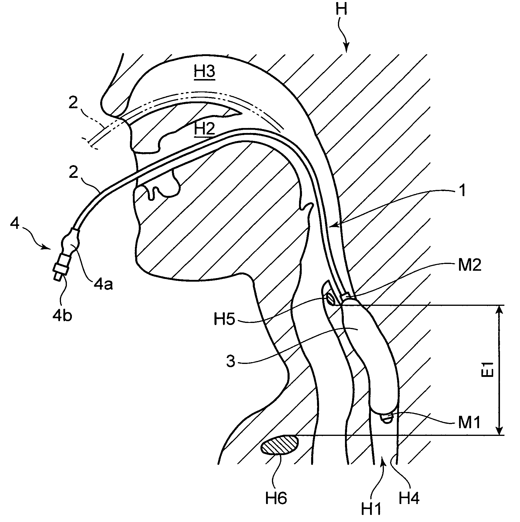
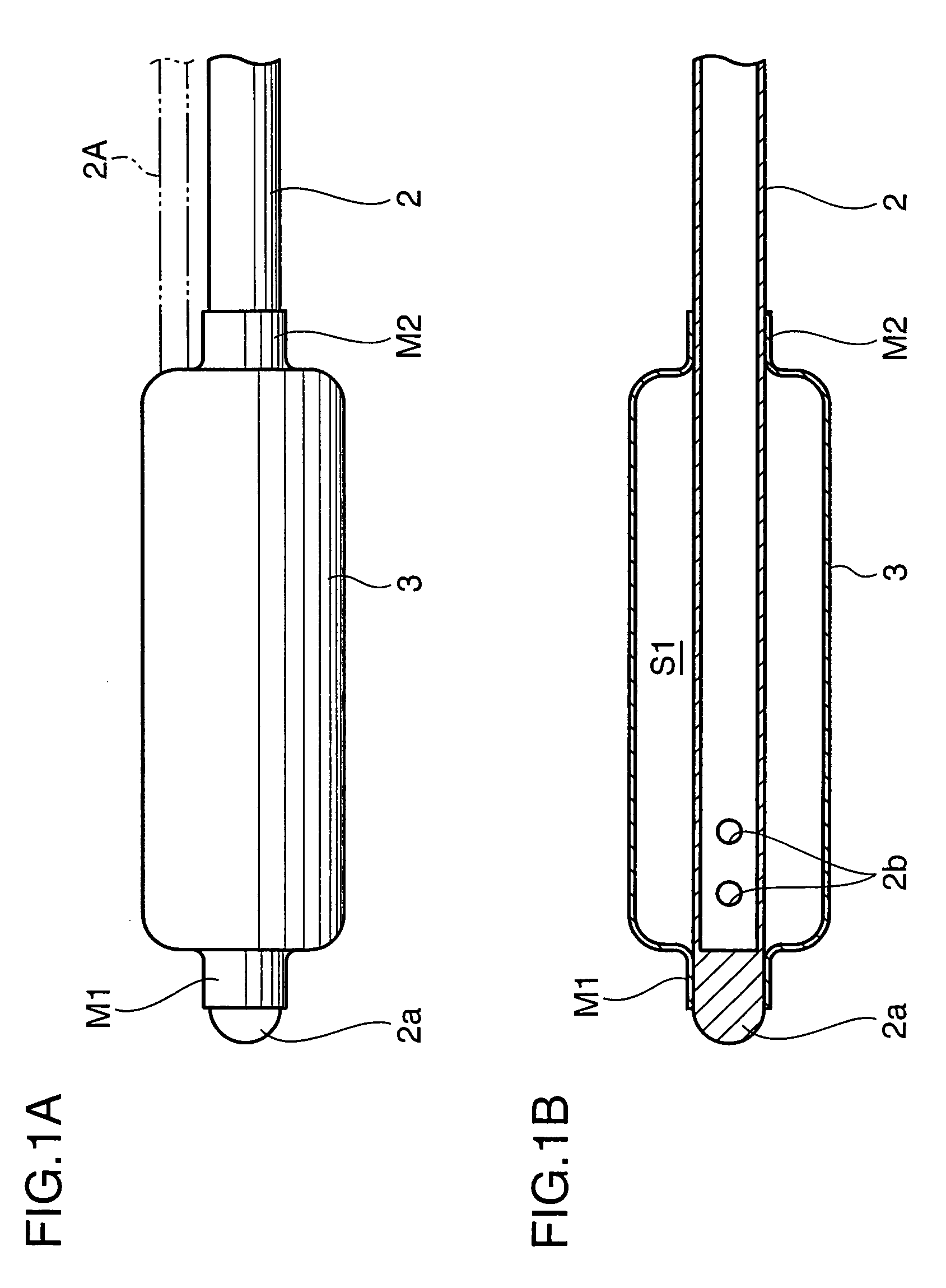
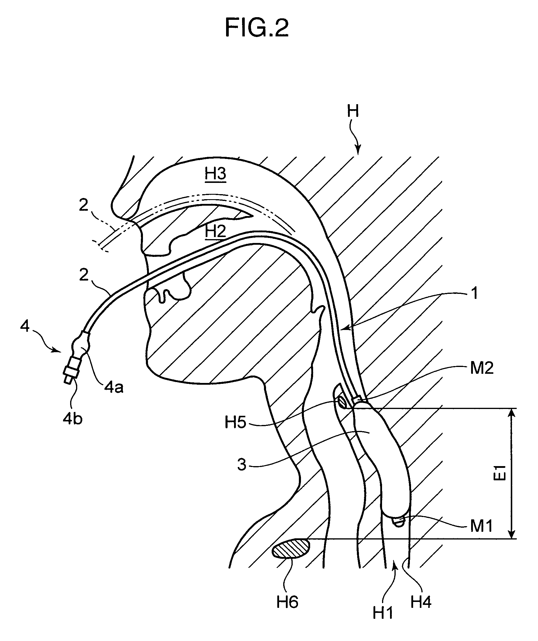
[0036]FIG. 1 shows a shape of the tip end of a brain cooling device according to the invention. FIG. 1A is a side view and FIG. 1B is a sectional side view. FIG. 2 is a sectional side view showing a state where the brain cooling device of FIG. 1 is inserted into a patient.

[0037]Referring to the respective drawings, a brain cooling device (hereinafter, referred to as the cooling device) 1 includes a tube (infusion and discharge means) 2, a cuff (storage portion) 3 provided to one end of the tube 2, and a port 4 provided to the other end on the opposite side of the cuff 3. Hereinafter, the tube 2 will be described on the assumption that the side provided with the cuff 3 is the tip end and the side provided with the port 4 is the base end.

[0038]The tube 2 is a tubular member made of synthetic resin, such as polyamide and polyvinyl chloride. Also, the tube 2 is closed by a bottom portion 2a at the tip end and is provided with plural side holes 2b (two side holes are illustrated in FIG. ...

second embodiment

[0062]FIG. 3 shows a shape of the tip end of a cooling device according to the invention. FIG. 3A is a plan view and FIG. 3B is a side view. FIG. 4 is a cross section taken on line IV-IV of FIG. 3B.

[0063]FIG. 5A is a sectional side view showing a state where an endotracheal tube is inserted into the patient to describe the procedure to insert the cooling device of FIG. 3 into a patient. FIG. 5B is a sectional side view showing a state where the cooling device is inserted to describe the procedure to insert the cooling device of FIG. 3 into the patient.

[0064]Referring to the respective drawings, a cooling device 5 includes the tube 2, a cuff 6 provided to the tip end of the tube 2, a pair of discharge tubes 7 extending from the base end of the cuff 6, and the port 4 provided to each of the base ends of the tube 2 and the discharge tubes 7.

[0065]The cuff 6 is a bag-shaped member made of silicone resin, flexible polyvinyl chloride, or the like. To be more concrete, the cuff 6 includes ...

third embodiment

[0086]FIG. 6 is a side view showing the overall configuration of a brain cooling system according to the invention. FIG. 7 shows the enlarged tip end of the brain cooling system of FIG. 6. FIG. 7A is a plane view and FIG. 7B is a bottom view. FIG. 8 is a cross section taken on line VIII-VIII of FIG. 7. FIG. 9 is a cross section taken on line IX-IX of FIG. 7. FIG. 10 is a sectional side view showing a state of use of the brain cooling system of FIG. 6.

[0087]Referring to the respective drawings, a brain cooling system 18 (hereinafter, referred to as the cooling system 18) is formed by combining a pharyngeal mask (airway maintaining member) 19 that allows a gas passage into the trachea H8 while blocking a gas passage into the esophagus H1 of the patient H, and a cooling device 20 that cools the esophagus H1 and the pharyngeal region T of the patient H.

[0088]To be more concrete, the pharyngeal region mask 19 includes a tube main body 21 formed in an almost circular arc shape, a connecto...


PUM


Abstract

A brain cooling device is provided to cool the brain sufficiently to the subcortical tissue in a short time. The device includes a cuff (3) capable of storing therein a cooled fluid and placeable in the esophagus (H1) of the patient (H) when inserted orally or transnasally. A tube (2) extends from the cuff (3) for infusing the fluid into the cuff (3) placed in the esophagus (H1) from outside the body of the patient H and discharging the fluid from the cuff (3). The cuff (3) has flexibility so as to inflate or deflate in response to infusion or discharge of the fluid and is configured in such a manner that when the fluid is infused therein while placed in the esophagus (H1), the cuff (3) that has been inflated comes into close contact with the inner wall (H4) of the esophagus (H1).

Description

BACKGROUND OF THE INVENTION[0001]1. Field of the Invention[0002]The present invention relates to a brain cooling device.[0003]2. Description of the Related Art[0004]In organisms such as a human body, an amount of oxygen supplied to the brain becomes insufficient due to a failure of the respiratory function or the circulatory function like in a cardiac arrest (hereinafter, referred to as the cardiac arrest state), and this insufficient oxygen supply is known to cause a death of brain cells, so-called ischemic neuron damage.[0005]Meanwhile, treatment for resuscitation from the cardiac arrest state, such as artificial respiration, is practiced on an organism in the cardiac arrest state. However, even in a case where the organism in the cardiac arrest state is resuscitated by this treatment, aftereffects are highly likely to occur in the brain due to the ischemic neuron damage.[0006]Under these circumstances, a treatment to cool the brain by lowering the body temperature of an organism ...

Claims


Application Information

Patent Timeline
Patent Type & Authority Applications(United States)
IPC IPC(8): A61F7/12
CPCA61F7/123A61F2007/0056A61M16/0459A61M16/0409A61M16/04A61M19/00A61M2205/3606A61M16/0443A61M16/0486
Inventor TAKEDA, YOSHIMASAMORITA, KIYOSHIYOSHIDA, KOUJIKOBAYASHI, TAKEHARU
Owner UNIV OKAYAMA
Why Eureka
Try Eureka