Self-steering axle suspension system having a rotary stabilizer mounted at a pivot joint associated with a tie rod

a self-steering axle and stabilizer technology, which is applied in the direction of shock absorbers, mechanical equipment, transportation and packaging, etc., can solve the problems of linear stabilizers that are relatively heavy, b>14/b> is relatively heavy, and requires high maintenance, so as to facilitate compliance, increase the payload capacity, and facilitate the effect of complian

Active Publication Date: 2009-07-16
HENDRICKSON USA L L C
View PDF7 Cites 7 Cited by
  • Summary
  • Abstract
  • Description
  • Claims
  • Application Information

AI Technical Summary

Benefits of technology

[0009]A rotary stabilizer designed in accordance with the principles of the present invention and used in a self-steering axle suspension system is preferably relatively lightweight, translating into increased payload capacity and more readily permitting compliance with relevant bridge weight and stress laws and regulations. The stabilizer is preferably relatively inexpensive, having fewer components than conventional stabilizers used in self-steering axle suspension systems. In addition, only a single stabilizer is required for control of the steerability of the suspension system in both steering directions. The stabilizer is preferably compact, fitting tight in relation to the axle or axle beam and acting directly about the king pin centerline. The stabilizer is preferably relatively low maintenance insofar as it includes a fully-enclosed housing and it is mounted above the axle in a position where it is less likely to be subjected to road debris and the like. Maintenance of the stabilizer is also relatively easy, as it is positioned above the king pin centerline in coaxial relationship therewith and is positioned above the axle or axle beam, permitting its relatively simple installation, removal and replacement. The stabilizer preferably includes material that resists velocity motion and the accompanying oscillations that would otherwise occur during road travel of the vehicle. The stabilizer also preferably includes material that provides for self-centering of the self-steering axle suspension system.

Problems solved by technology

Linear stabilizers, such as those illustrated in FIG. 1 as reference numerals 12, 14 are relatively heavy, expensive, bulky and require high maintenance.
With regard to the latter drawback, linear stabilizers are subject to damage due to road debris and the like.
For this reason, enclosed housing designs have been implemented; however, such designs have only reduced but have not eliminated the maintenance required for linear stabilizers.
In addition, maintenance operations, especially out in the field, are cumbersome and correspondingly difficult and time consuming.

Method used


Image

  • Self-steering axle suspension system having a rotary stabilizer mounted at a pivot joint associated with a tie rod
  • Self-steering axle suspension system having a rotary stabilizer mounted at a pivot joint associated with a tie rod
  • Self-steering axle suspension system having a rotary stabilizer mounted at a pivot joint associated with a tie rod

Examples


Embodiment Construction

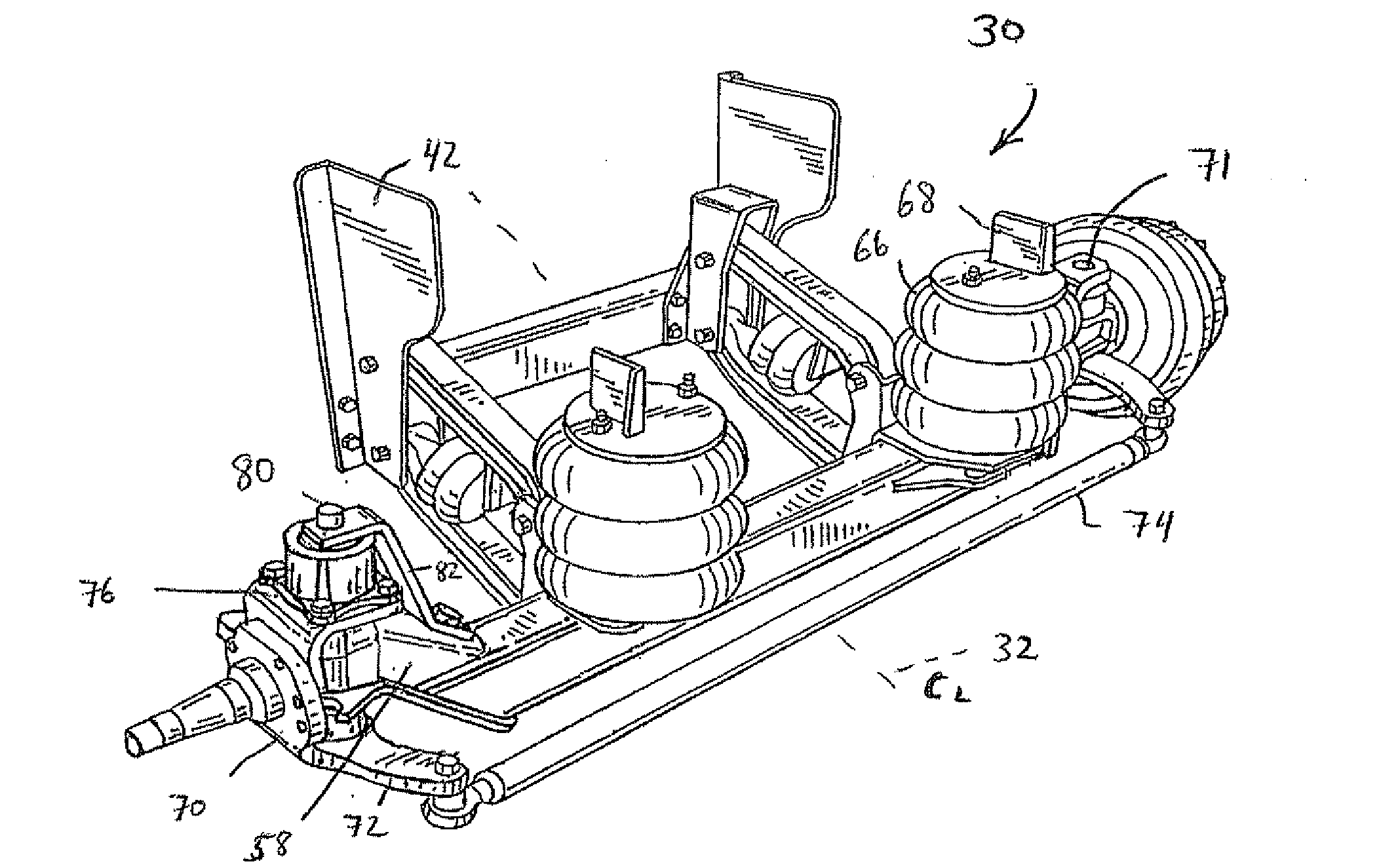
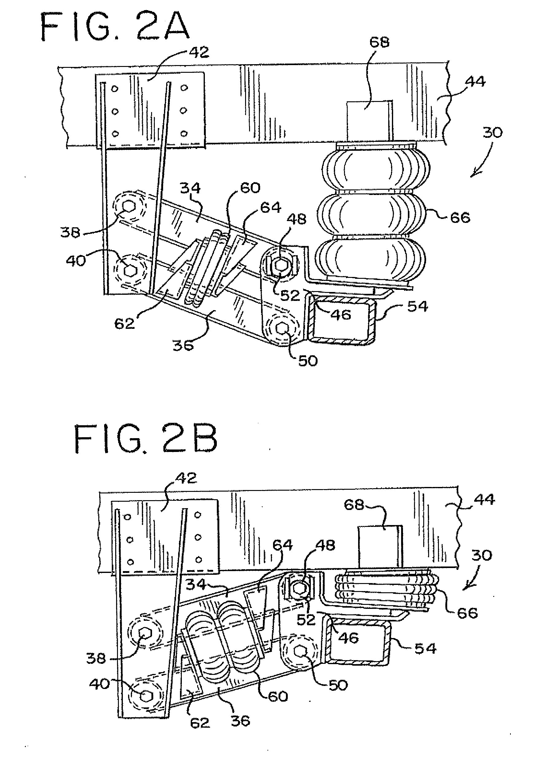
[0026]FIGS. 2A, 2B and 3 illustrate a self-steering axle suspension system generally indicated by reference numeral 30. The illustrated self-steering axle suspension system 30 is a self-steering auxiliary lift-axle type of suspension system having a parallelogram, trailing arm geometry. The axle suspension system 30 is preferably a relatively lightweight suspension designed to permit compliance with any applicable bridge weight and stress regulations, such as the Federal Bridge Formula associated with relevant laws and regulations applicable within the United States of America.

[0027]While suspension system 30 is described as having these additional features, it will be appreciated that the present invention applies to all self-steering axle suspension systems for wheeled vehicles.

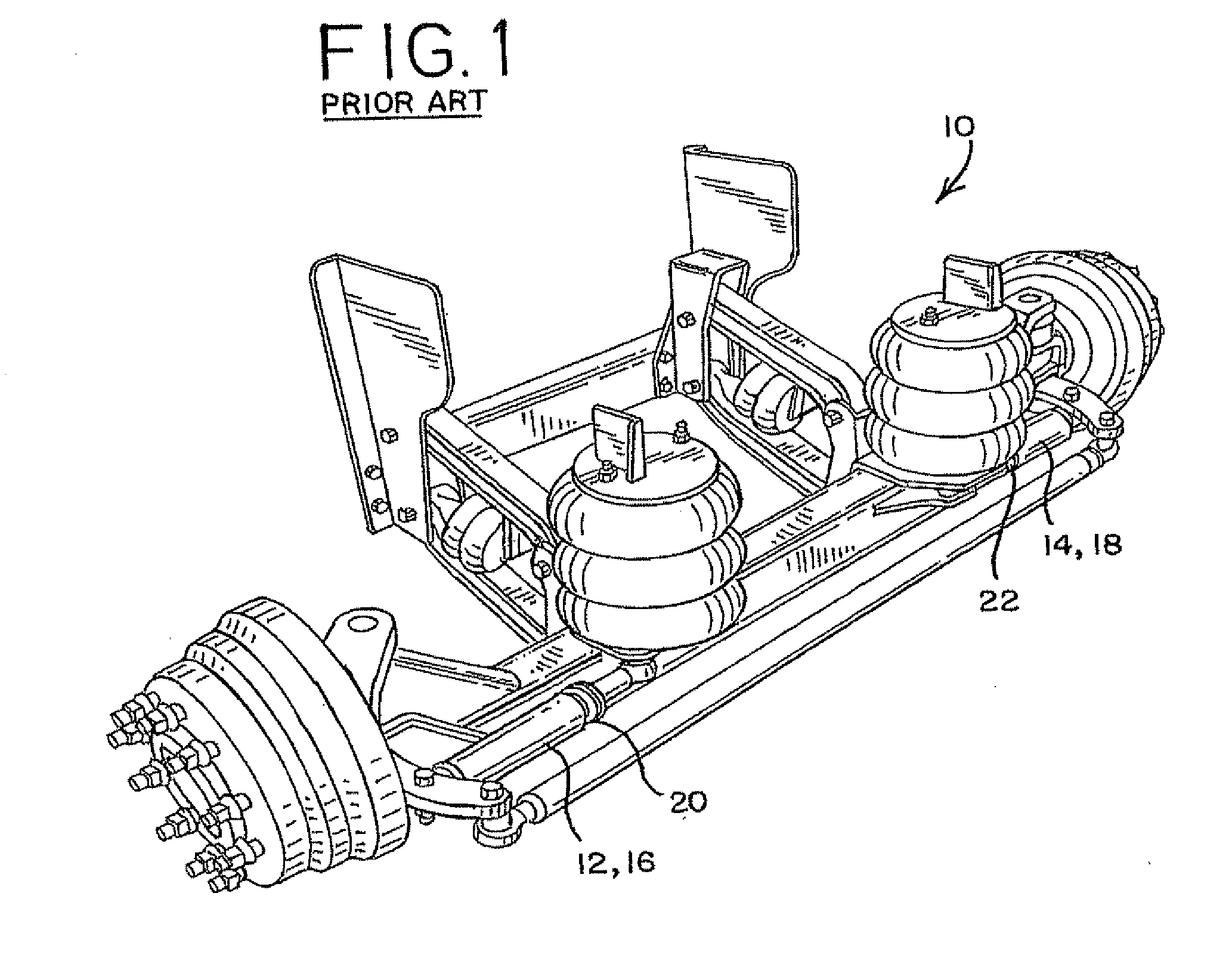
[0028]The suspension 30 illustrated in the figures is representative of an embodiment of the steerable, wheel-bearing lift axle suspension systems disclosed in U.S. Pat. No. 5,403,031 and U.S. Pat. No. 5,62...


PUM


Abstract

A self-steering axle suspension system utilizing a rotary damper coaxially aligned with and acting directly about the king pin centerline on one side of the vehicle is disclosed. Alternatively, the rotary damper may be mounted at, and axially aligned with, a pivot joint joining a steering knuckle with the tie rod. When used as such, the rotary damper constitutes a rotary stabilizer. The rotary stabilizer is used to control the steerability of the self-steering axle suspension system and has a self-centering axle mechanism incorporated therein.

Description

CROSS-REFERENCE TO RELATED APPLICATIONS[0001]This patent application is a continuation-in-part patent application of U.S. patent application Ser. No. 12 / 107,493, filed Apr. 22, 2008, which is a continuation patent application of U.S. patent application Ser. No. 11 / 459,212, filed Jul. 21, 2006 (now U.S. Pat. No. 7,360,773).BACKGROUND OF THE INVENTION[0002]The present invention relates generally to stabilizers used in self-steering axle suspension systems for wheeled vehicles. More particularly, the present invention relates to a rotary damper used as a stabilizer in self-steering axle suspension systems for wheeled vehicles to suppress oscillations during travel of the vehicle and to control the steerability of the self-steering axle suspension system.[0003]Self-steering axle suspension systems in the medium and heavy duty truck and semitrailer industry are known. Typically, such suspensions are made self-steering by adjusting the pitch or caster angle of the wheels so that the drag ...

Claims


Application Information

Patent Timeline
Patent Type & Authority Applications(United States)
IPC IPC(8): B62D61/12
CPCB60G9/003B60G11/27B60G2200/314B60G2202/152B60G2204/4702B62D7/144B62D7/18B62D7/22F16F1/445F16F9/145
Inventor GOTTSCHALK, MICHAEL J.
Owner HENDRICKSON USA L L C
Why Eureka
Try Eureka