
Method for regulating an internal combustion engine, computer program and control unit

a technology of internal combustion engine and computer program, applied in the direction of electrical control, process and machine control, etc., can solve the problems of comparatively low residual gas compatibility, difficult to regulate dynamic engine operation, and large challenge in dynamic engine operation regulation, so as to eliminate statistical variations in combustion position features, reduce the effect of sensitiveness

Inactive Publication Date: 2009-07-16
ROBERT BOSCH GMBH
View PDF9 Cites 61 Cited by
  • Summary
  • Abstract
  • Description
  • Claims
  • Application Information

AI Technical Summary

Benefits of technology

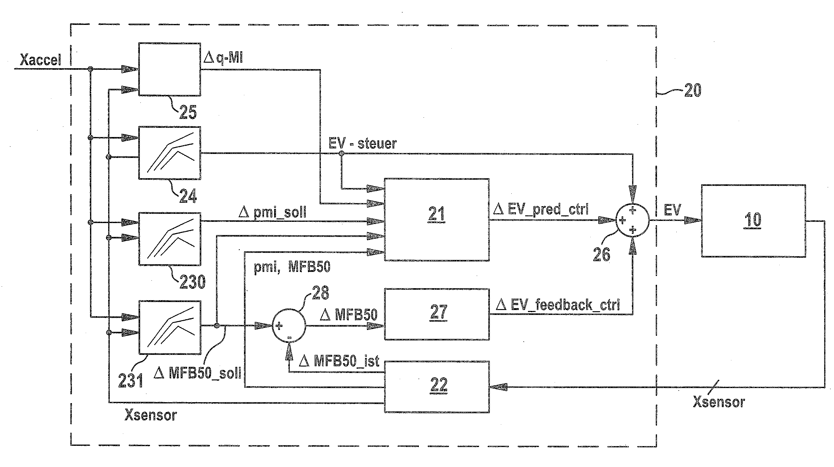
[0016]The present invention utilizes the concept of subjecting the combustion process of an internal combustion engine with auto-ignition to predictive closed-loop control, using a combustion position feature as a reference variable. In the case of a gasoline engine operated in CAI operation or in SI operation depending on the operating point (so-called CAI engine), improved regulation may therefore be achieved in dynamic operation since the predictive closed-loop control takes into consideration the coupling of the combustion process from cycle to cycle and thus makes rapid regulation possible, with misfiring being avoided, not only in the case of load changes but also in the case of changing between CAI operation and SI operation. Additionally, in the case of diesel engines, advantageous regulation of the combustion process at load changes may be implemented using this predictive closed-loop control. Another reason why a combustion position feature is used in the present invention as a reference variable is that the combustion position is closely linked to noise development, and therefore the noise behavior of the engine may be controlled indirectly by suitable open-loop / closed-loop control of the combustion position. It is thus possible to avoid troublesome noise development during a change in the type of operation or also in the case of a load change within a type of operation.
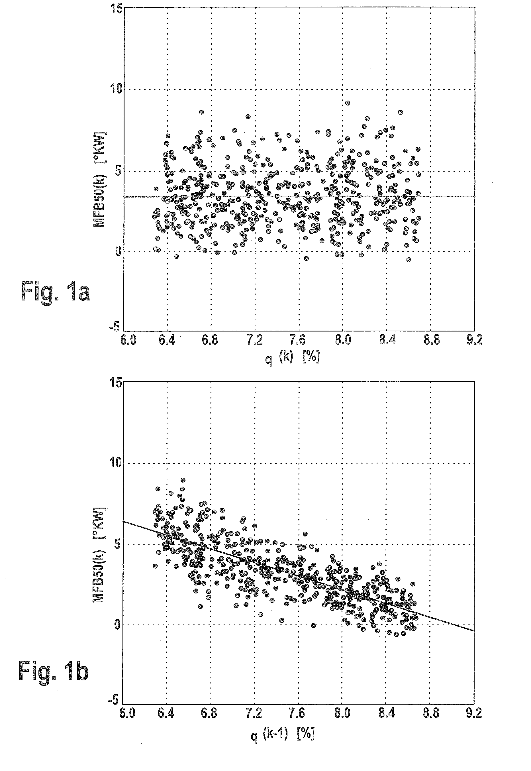
[0031]To determine the offset correction value it is also possible to subject the difference determined in step (e) to low-pass filtering. It is also possible to average the difference determined in step (e) over a plurality of combustion cycles in order to determine the offset correction value. Accordingly, it is possible to eliminate statistical variations in the combustion position feature.

Problems solved by technology

In CAI engines, regulation of dynamic engine operation is a great challenge.
Changes to the operating point in dynamic engine operation should take place as steadily as possible with respect to torque and noise, which, however, proves difficult on account of the factors described below:
A further difficulty arises when changing between SI operation and CAI operation: In SI operation, the residual gas compatibility is comparatively low and therefore as little residual gas as possible should be retained in the cylinder.
It is therefore not possible for the proportion of residual gas to be gradually raised “in preparation”, as it were, before a change from SI operation to CAI operation, and conversely, when changing from CAI operation to SI operation, the proportion of residual gas may not already be lowered in advance since this would lead to considerable disturbance of the combustion behavior to the point of misfiring.
Consequently, combustion takes place too early, that is, is too loud to the point of knocking.
That in turn means that the change in type of operation entails troublesome noise development.
At an abrupt change from a lower to a higher load point, too little residual gas and / or residual gas that is too cold is retained in the first cycle following the load change, which leads to combustion that is too late (compared with the desired value) to the point of misfiring.

Method used


Image

  • Method for regulating an internal combustion engine, computer program and control unit
  • Method for regulating an internal combustion engine, computer program and control unit
  • Method for regulating an internal combustion engine, computer program and control unit

Examples


Embodiment Construction

[0042]Exemplary embodiments of a method and control unit according to the present invention will be explained with reference to the accompanying drawings. Unless stated otherwise, identical or functionally identical elements have been provided with the same reference numerals throughout the figures of the drawings.

[0043]The present invention will be explained with reference to a gasoline engine that is operable selectively or in dependence on operating point in CAI operation and in SI operation. It is, however, generally applicable to engines that are operable at least in a part-load range in an operating mode with auto-ignition, that is to say, for example, that the present invention is also applicable to diesel engines.

[0044]In accordance with one exemplary embodiment, first the desired value of the combustion position, which is a feature (combustion position feature) of the combustion process, is determined and is then fed as a reference variable to a predictive closed-loop contr...


PUM


Abstract

A method for regulating an internal combustion engine that is operable, at least in a part-load range, in an operating mode with auto-ignition and a combustion process of which is influenced by a manipulated variable, the method includes the steps of determining a desired value of a combustion position feature of the combustion process; determining the manipulated variable by predictive closed-loop control based on a modeling of the combustion position feature as a function of the manipulated variable in the combustion process; and determining, as the manipulated variable, a value at which the difference between the desired value of the combustion position feature and a model-based predicted combustion position feature is minimized.

Description

FIELD OF THE INVENTION [0001]The present invention relates to a method for regulating an internal combustion engine, especially an internal combustion engine that is operable, at least in a part-load range, in an operating mode with auto-ignition. The present invention further relates to a computer program and to a control unit for carrying out such a method.BACKGROUND INFORMATION [0002]A comparatively new development that has become known among gasoline engine combustion methods is the HCCI (Homogeneous Charge Compression Ignition) method, which is also referred to as the CAI (Controlled Auto Ignition) method. The CAI method has a significant potential to save fuel compared to conventional spark-ignition operation.[0003]CAI engines operate with a homogeneously (uniformly) distributed mixture of fuel and air. Ignition is initiated in this case by the rising temperature as compression takes place and by any free radicals and intermediates or precursors of the preceding combustion pro...

Claims


Application Information

Patent Timeline
Patent Type & Authority Applications(United States)
IPC IPC(8): F02D41/00
CPCF02D35/023F02D35/028F02D41/0002F02D41/006F02D41/008F02D41/1454F02D2041/1412F02D41/3064F02D41/402F02D2041/001F02D2041/1433F02D35/024F02D41/3035
Inventor LOEFFLER, AXELHAERING, JUERGENFISCHER, WOLFGANGKARRELMEYER, ROLANDGRAF, GERALD
Owner ROBERT BOSCH GMBH
Learn More