Wood Beam System

Inactive Publication Date: 2009-07-23
BRYANT JACOB
View PDF12 Cites 0 Cited by
  • Summary
  • Abstract
  • Description
  • Claims
  • Application Information

AI Technical Summary

Benefits of technology

[0005]The present invention is a wood beam system that is light weight and easily attaches to any type of building surface. The wood beam system is created by coupling two or more wood beam pieces together and fastening the pieces to anchor plates that are attached to

Problems solved by technology

This can be an expensive and time consuming process.
This distracts from the aesthetic appeal of the beams and their overall quality.
Second, because these beams are made of composite material,

Method used


Image

  • Wood Beam System
  • Wood Beam System
  • Wood Beam System

Examples


Embodiment Construction

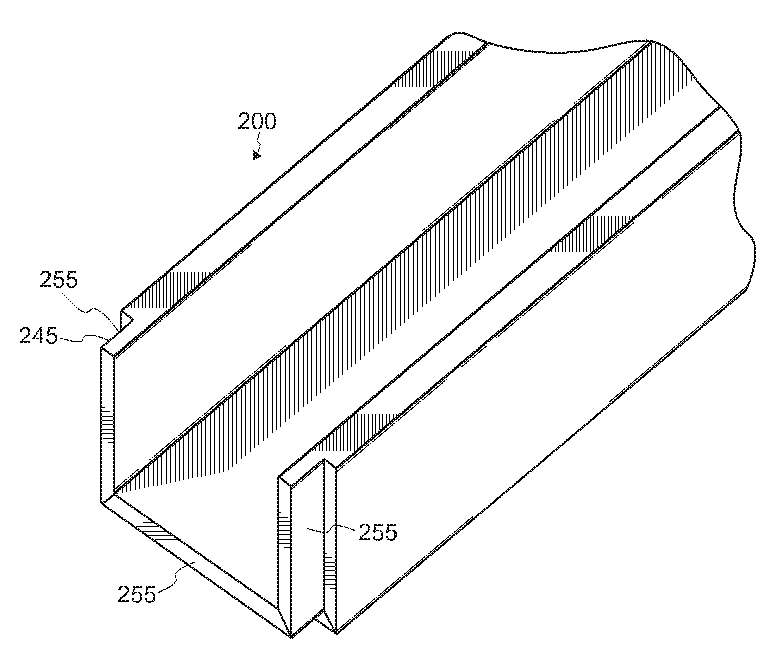
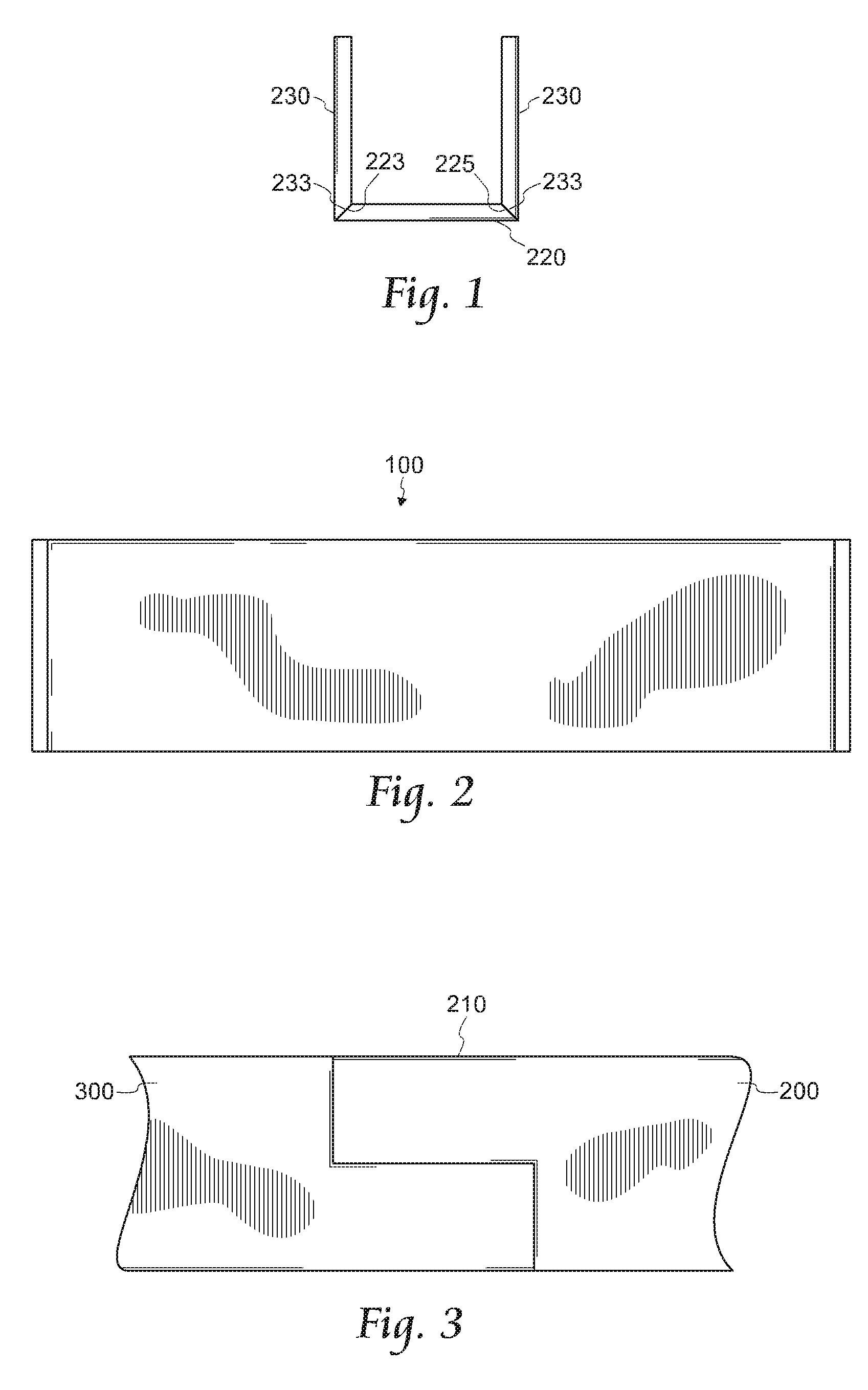
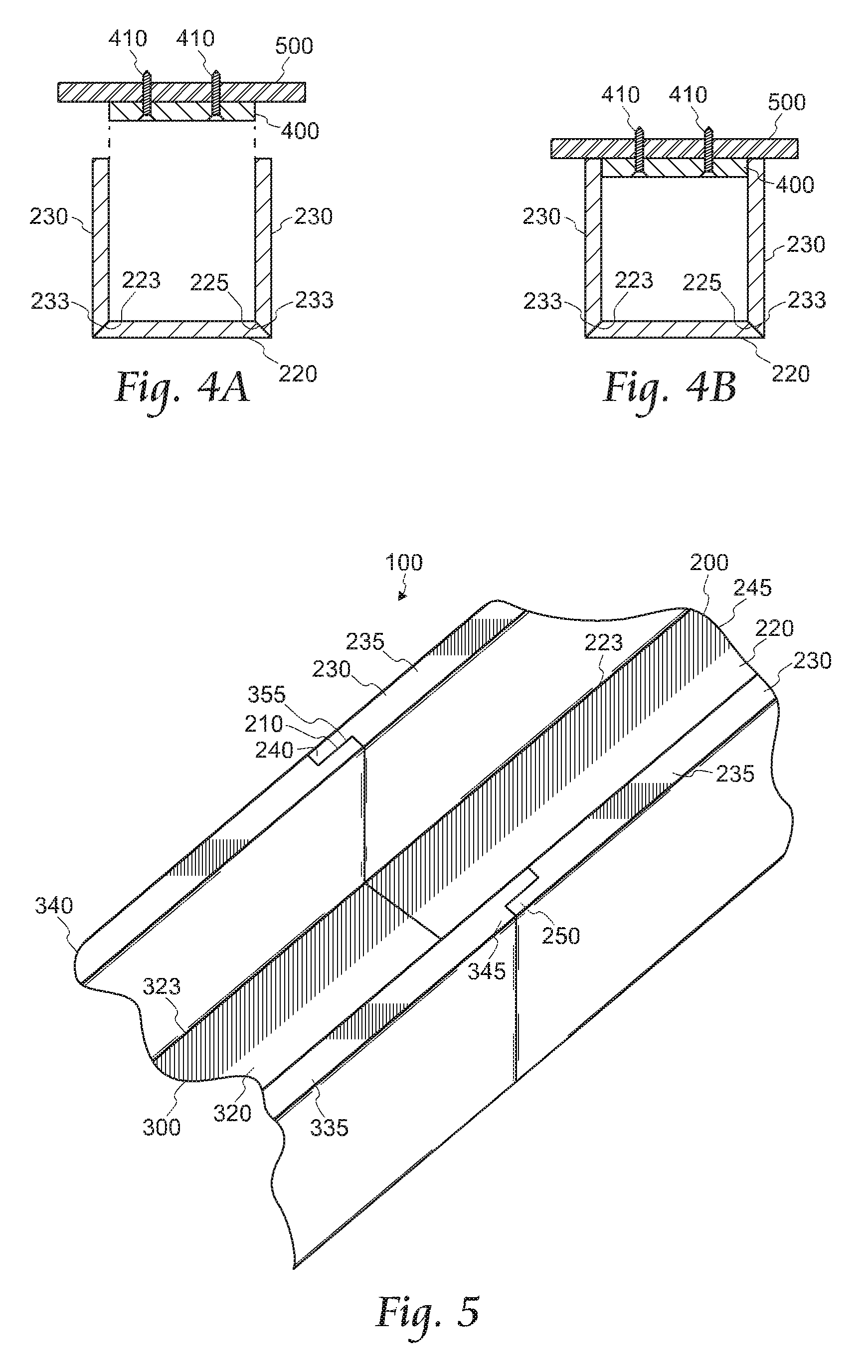
[0022]FIG. 5 shows a top view of the preferred embodiment of the beam system 100. As seen in FIGS. 4A, 4B, and 5, the beam system 100 comprises a first beam piece 200, a second beam piece 300, and an anchor plate 400. These pieces combined together create the beam system 100 disclosed. Preferably, the first beam piece 200 and the second beam piece 300 are made of real wood and are coupled together, as shown in FIG. 3, using a shiplap joint 210 at the connection point.

[0023]In the preferred embodiment of the invention, the first beam piece 200 further comprises a bottom plate 220 and two vertical plates 230, as shown in FIGS. 5 and 7. The bottom plate 220 has a first edge 223 and a second edge 225 that are mitered. The two vertical plates 230 both include a top edge 233 and a bottom edge 235. Only the top edges 233 of the vertical plates 230 are mitered in the preferred embodiment. The first edge 223 of the bottom plate 220 is coupled to the top edge 233 of the first vertical plate 2...


PUM


Abstract

The present invention is a light weight decorative wood beam system. The wood beam system is comprised of at least two wood beam pieces. The wood beam pieces each have a bottom plate and two vertical plates that form a three-sided, hollow box. Each wood beam piece comprises an end with a male dado and an end with a female dado. The male and female dado ends fit over each other to create a shiplap joint. Anchor plates are fastened into a building surface and support the wood beam system. Because the wood beam system is light weight, it does not require a special anchoring system to support the real wood beams.

Description

FIELD OF THE INVENTION[0001]The present invention relates generally to the field of woodworking. More specifically, the present invention is a system of lightweight real wood beams used as ornamentation on or in a structure.BACKGROUND OF THE INVENTION[0002]Currently, if an individual wishes to install real wood beams on a ceiling or other surface of a building, the individual must ensure that the building structure is capable of supporting the weight of the real wood beams. If the building is being newly built, there must be proper support structures included in the frame of the building. Additionally, if the building is pre-existing and the real wood beams are being added into the building, the individual must make sure that the proper support structures exist or that they are added to the building. This can be an expensive and time consuming process.[0003]Various techniques have been disclosed in U.S. Pat. No. 3,890,415 (Hull), U.S. Pat. No. 3,277,624 (Cornell), U.S. Pat. No. 4,42...

Claims


Application Information

Patent Timeline
IPC IPC(8): E04C3/12
CPCE04C3/12E04B2009/062
Inventor BRYANT, JACOB
Owner BRYANT JACOB
Why Eureka
Try Eureka