
Braking control device for vehicle

a technology for controlling devices and brakes, applied in the direction of process and machine control, instruments, tractors, etc., can solve the problems of unintended braking force or driving force being applied to the wheel, lateral force may change, etc., and achieve the effect of smooth turning a corner

Active Publication Date: 2009-07-23
TOYOTA JIDOSHA KK
View PDF29 Cites 22 Cited by
  • Summary
  • Abstract
  • Description
  • Claims
  • Application Information

AI Technical Summary

Benefits of technology

The present invention provides a brake control device for vehicles that can appropriately perform brake control even when a vehicle is in a center differential lock mode or a direct four-wheel drive mode. The device includes a turning condition detection unit, a braking amount setting unit, a brake control unit, and a road surface friction coefficient estimation unit. The braking amount setting unit changes the upper limits of braking amounts for the respective wheels based on the road surface friction coefficient, and the brake control unit applies braking forces to the wheels accordingly. This allows for stable behavior control of the vehicle when turning corners, and can also improve stability control in situations where the vehicle is in a center differential lock mode or a direct four-wheel drive mode.

Problems solved by technology

Therefore, if a vehicle behavior control device is used while a center differential is locked, an unintended braking force or driving force may be applied to a wheel, and the balance between the front and rear wheels in terms of the anti-spin moment and the tire lateral force may change.

Method used


Image

  • Braking control device for vehicle
  • Braking control device for vehicle
  • Braking control device for vehicle

Examples


Embodiment Construction

[0048]The best mode for carrying out the invention is described based on the following embodiments with reference to the accompanying drawings.

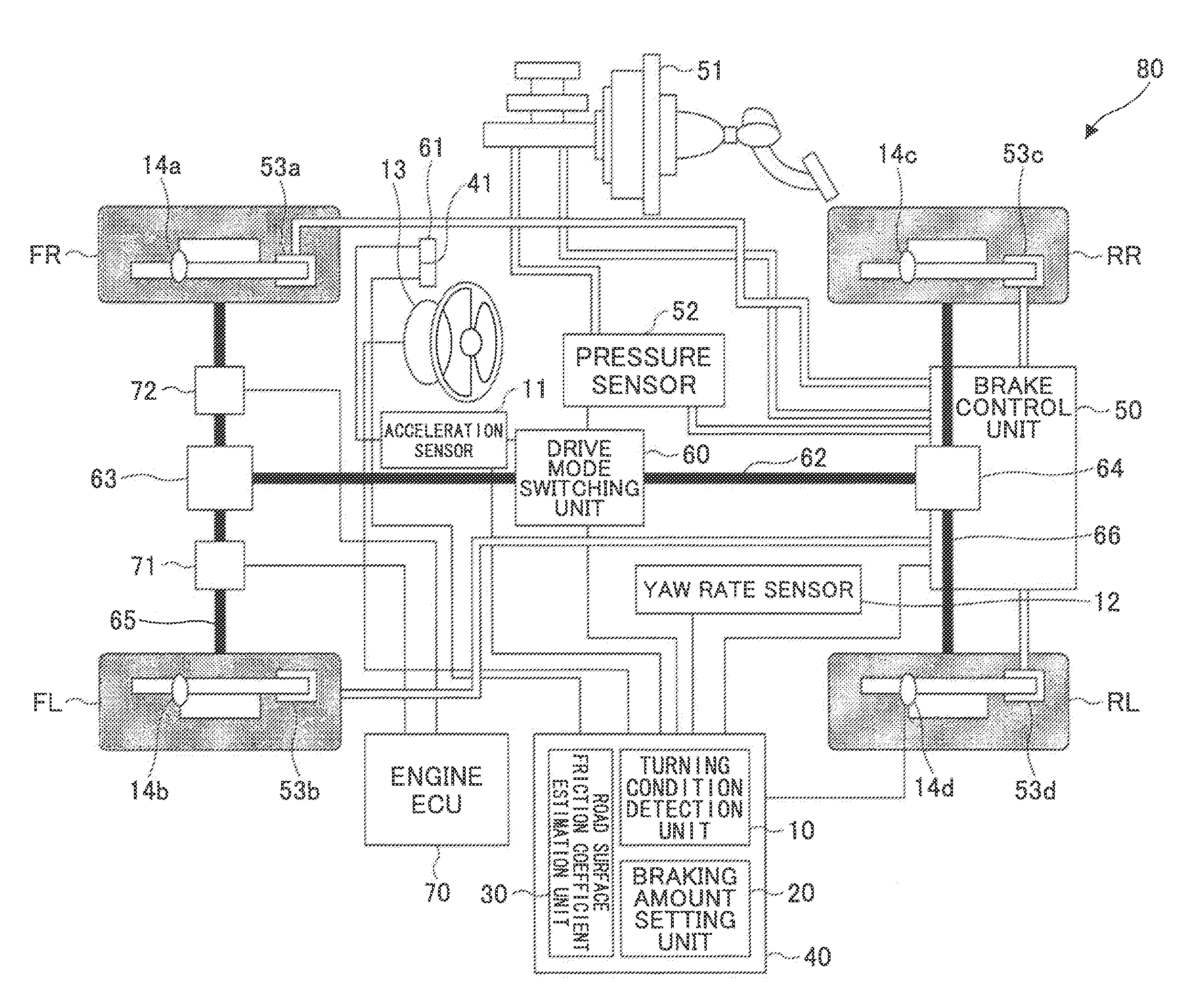
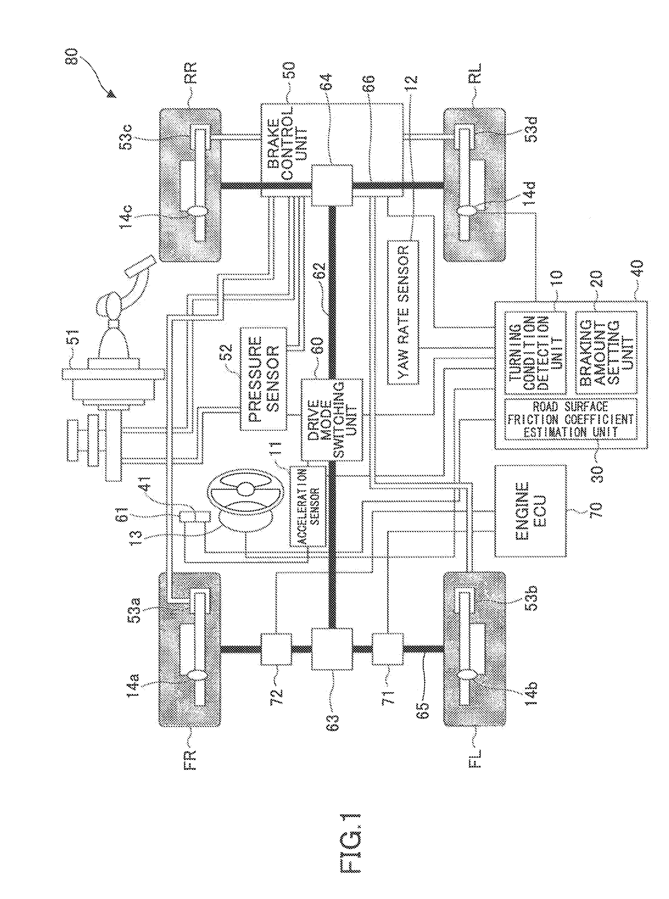
[0049]FIG. 1 is a schematic diagram of a brake control device 80 for a vehicle according to an embodiment of the present invention. The brake control device 80 includes a turning condition detection unit 10, a braking amount setting unit 20, a road surface friction coefficient estimation unit 30, and a brake control unit 50 such as a brake actuator.

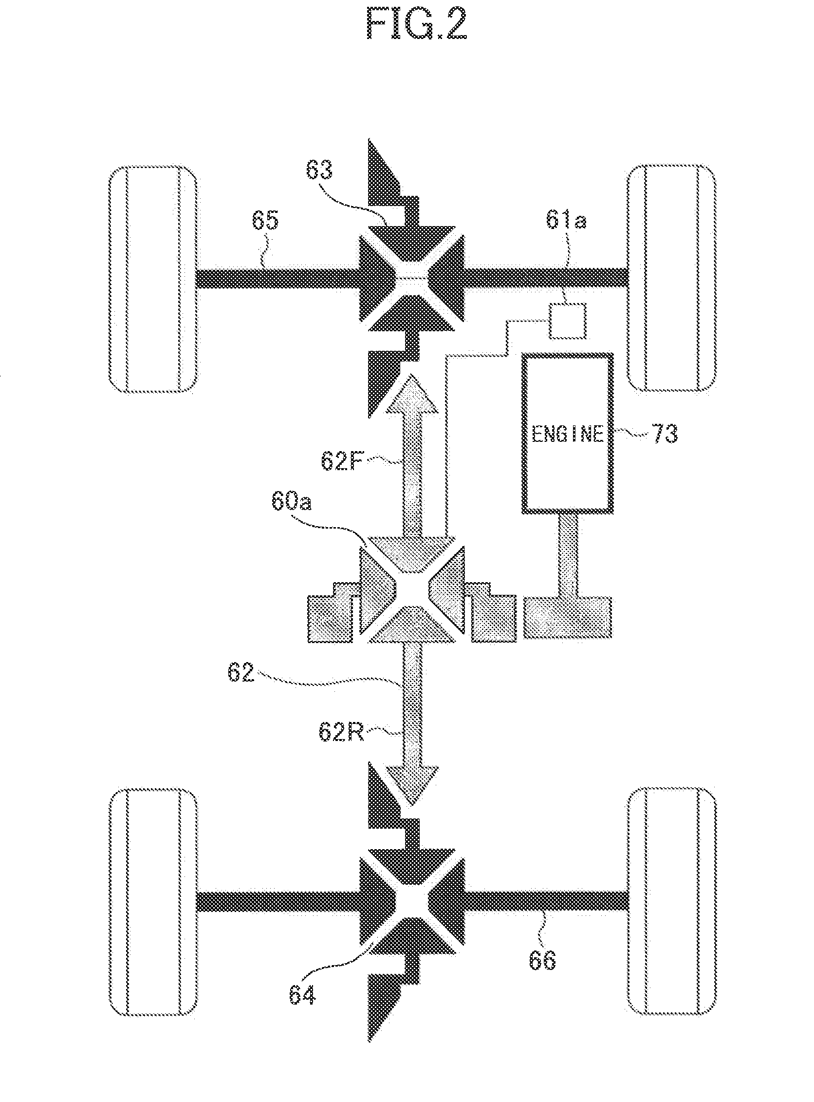
[0050]Components of a vehicle that are in connection with the brake control device 80 include a front differential 63, a rear differential 64, a propeller shaft 62 connected to the front and rear differentials 63 and 64, a front axle 65 connected to the front differential 63, front wheels FR and FL connected to the front axle 65, a rear axle 66 connected to the rear differential 64, and rear wheels RR and RL connected to the rear axle 66. In this embodiment, the vehicle may be a full-time four-whee...


PUM


Abstract

A brake control device that controls braking forces applied to wheels to stabilize the behavior of a vehicle turning a corner, and includes a turning condition detection unit detecting a turning condition of the vehicle; a braking amount setting unit setting braking amounts for the respective wheels based on the turning condition detected by the turning condition detection unit; a brake control unit applying braking forces to the wheels according to the braking amounts set by the braking amount setting unit; and a road surface friction coefficient estimation unit estimating a road surface friction coefficient of the road on which the vehicle is running. The braking amount setting unit changes upper limits of the braking amounts for the respective wheels according to the road surface friction coefficient when the vehicle is in a center differential lock mode or a direct four-wheel drive mode.

Description

TECHNICAL FIELD[0001]The present invention generally relates to a brake control device for a vehicle. More particularly, the present invention relates to a brake control device for stabilizing the behavior of a full-time four-wheel drive vehicle in a center differential lock mode or of a part-time four-wheel drive vehicle in a direct four-wheel-drive mode.BACKGROUND ART[0002]Vehicle behavior control devices control braking forces applied to individual wheels of a vehicle turning a corner according to the behavior of the vehicle. Meanwhile, when a center differential of a vehicle is locked, the rotational speeds of the rear wheels are restricted by those of the front wheels. Therefore, if a vehicle behavior control device is used while a center differential is locked, an unintended braking force or driving force may be applied to a wheel, and the balance between the front and rear wheels in terms of the anti-spin moment and the tire lateral force may change. Patent document 1 disclos...

Claims


Application Information

Patent Timeline
Patent Type & Authority Applications(United States)
IPC IPC(8): B60T8/1755
CPCB60T2201/14B60T8/1755
Inventor YAMADA, YOSHIHISAKOBAYASHI, YASUSHITAKASU, TATSUSHISHIMOGA, KOTA
Owner TOYOTA JIDOSHA KK
Learn More