
Attachable wireless charging device

a wireless charging and wireless charging technology, applied in the direction of resistive material coating, coupling device connection, safety/protection circuit, etc., can solve the problems of deteriorating the performance of wireless charging and wireless charging cannot be widely accepted

Active Publication Date: 2009-07-23
YEH MING HSIANG
View PDF0 Cites 38 Cited by
  • Summary
  • Abstract
  • Description
  • Claims
  • Application Information

AI Technical Summary

Benefits of technology

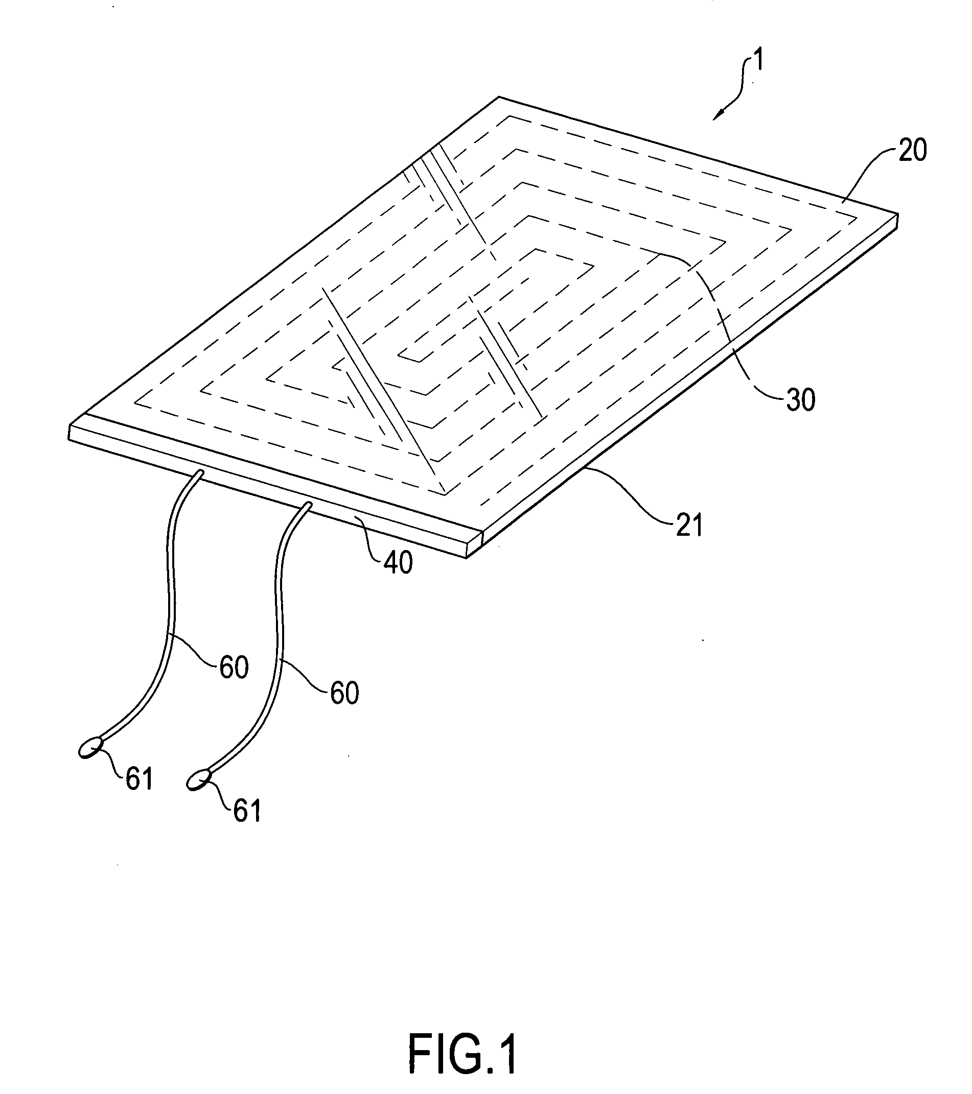
[0004]A primary objective of the present invention is to provide an attachable wireless charging device that comprises a combination of a carrier board, a receiving coil, a circuit board, and at least two conductive wires, wherein the receiving coil functions to receive electrical power transmitted from a power source transmitter in a wireless manner to realize wireless charging operation and the carrier board comprises an adhesive layer is externally attachable to an outer casing of a rechargeable battery and comprising conductive wires for electrical engagement with electrodes of the battery to effect wireless-receiving of electrical power and direct charging power to the battery whereby the problem of being shielded by an outer casing is eliminated and the practicability and convenience of the present invention is enhanced.
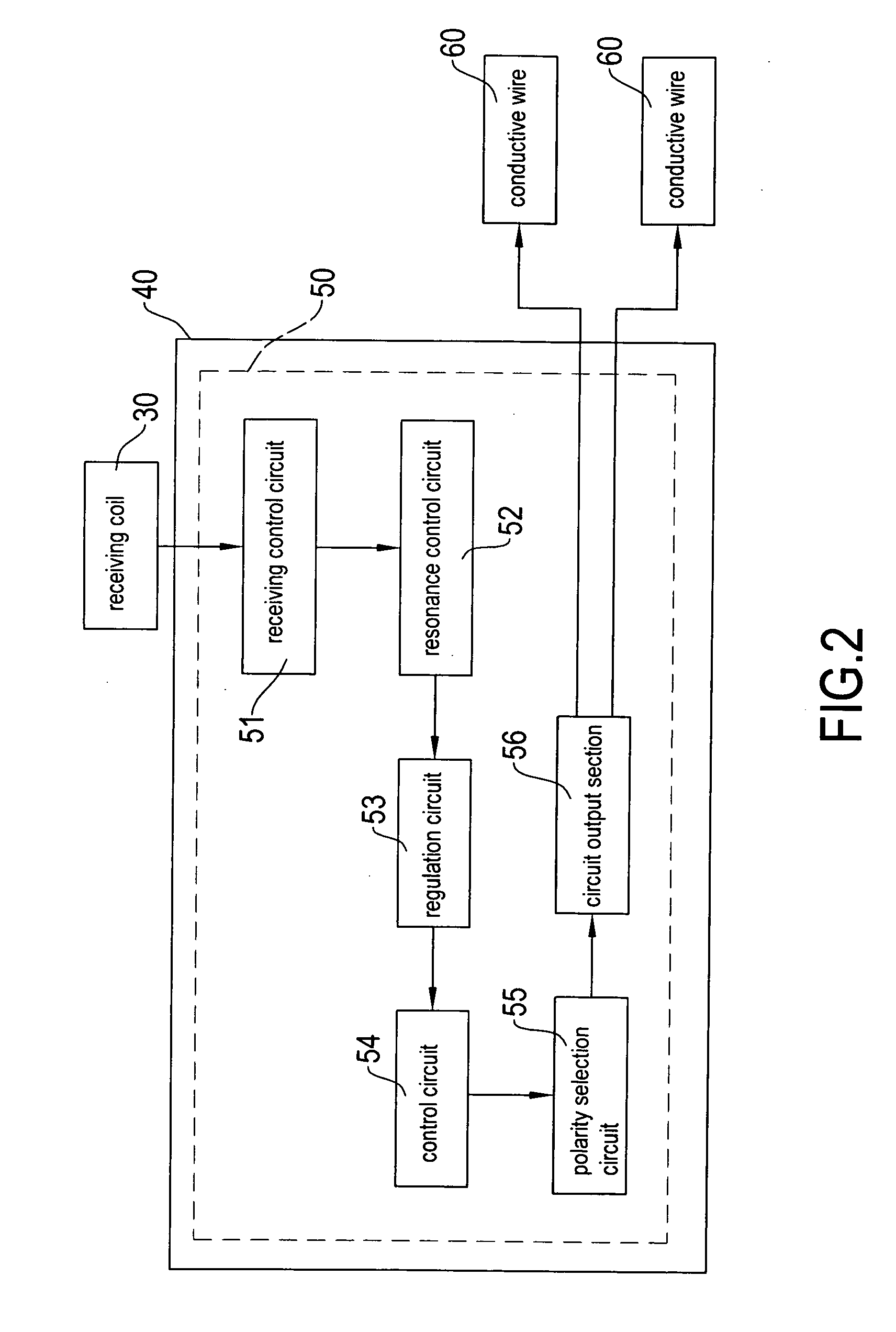
[0005]Another objective of the present invention is to provide an attachable wireless charging device that comprises a combination of a carrier board, a receiving coil, a circuit board, and at least two conductive wires, wherein the circuit board has a power receiving circuit that comprises a polarity selection circuit functioning to automatically determine the polarities through which charging operation is performed to thereby ensure charging protection for a rechargeable battery by preventing a rechargeable battery from being damaged due to reversed connection of the polarities, thereby enhancing the practicability and convenience of the present invention.
[0006]A further objective of the present invention is to provide an attachable wireless charging device that comprises a combination of a carrier board, a receiving coil, a circuit board, and at least two conductive wires, wherein the carrier board can be printed with various patterns to provide a function of advertisement, thereby enhancing the practicability and convenience of the present invention.

Problems solved by technology

Such an arrangement causes a problem that the device enclosure is often made of a material comprising ferrous materials or aluminum or metal electroplating layers, which shield the transmission of wireless charging signals, thereby deteriorating the performance of wireless charging.
As a consequence, the wireless charging cannot be widely accepted.

Method used


Image

  • Attachable wireless charging device
  • Attachable wireless charging device
  • Attachable wireless charging device

Examples


Embodiment Construction

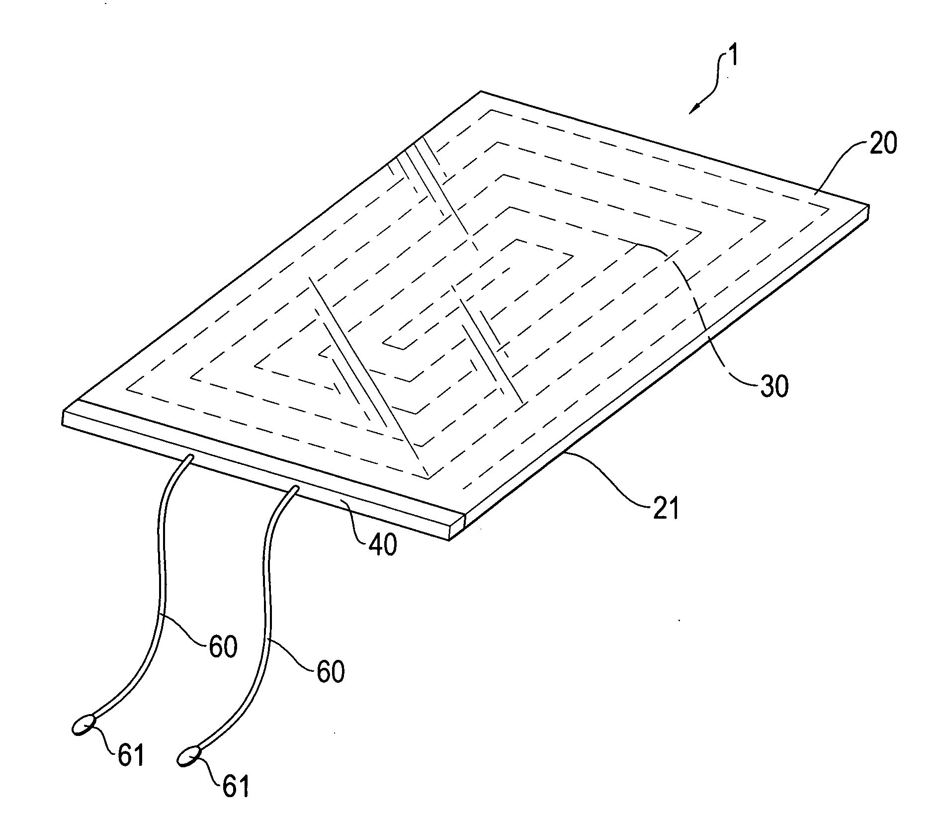
[0016]With reference to FIGS. 1-4, the present invention provides an attachable wireless charging device, generally designated at 1. The wireless charging device 1 of the present invention comprises a carrier board 20, a receiving coil 30, a circuit board 40, and at least two conductive wires 60. The carrier board 20 has a back surface on which a layer of adhesive 21 is coated. The adhesive layer 21 preferably comprises a repeatedly attachable adhesive for repeatedly attaching the wireless charging device 1 to for example a rechargeable battery to be charged. The receiving coil 30 is formed in the carrier board 20. The circuit board 40 is mounted to one side of the carrier board 20. The circuit board 40 comprises a power receiving circuit 50, which is comprised of a receiving control circuit 51, a resonance control circuit 52, a regulation circuit 53, a control circuit 54, a polarity selection circuit 55, and a circuit output section 56, which are electrically and sequentially conne...


PUM

PropertyMeasurementUnit
Polarityaaaaaaaaaa
Flexibilityaaaaaaaaaa
Electrical conductoraaaaaaaaaa

Abstract

An attachable wireless charging device includes a carrier board, a receiving coil, a circuit board, and at least two conductive wires. The carrier board has a back surface on which an adhesive layer is coated. The receiving coil is formed in the carrier board. The circuit board is mounted to one side of the carrier board and includes a power receiving circuit, which includes a receiving control circuit, a resonance control circuit, a regulation circuit, a control circuit, a polarity selection circuit, and a circuit output section, which are electrically and sequentially connected. Electrical connection is established between the receiving control circuit and the receiving coil. The at least two conductive wires are arranged at one side of the circuit board and are electrically connectable with the circuit output section of the circuit board. As such, an attachable wireless charging device featuring automatic determination of polarity connection is provided.

Description

FIELD OF THE INVENTION[0001]The present invention relates to an attachable wireless charging device, and in particular to an externally attachable charging device that comprises a combination of a carrier board, a receiving coil, a circuit board, and at least two conductive wires that features convenience of wireless charging, high charging performance without being shielded by an outer casing, automatic determination of polarity connection, repeated attachability, non-site-constrained, chargeability, and also offering a function of advertisement, and is applicable to various batteries and electronic devices.BACKGROUND OF THE INVENTION[0002]The development of wireless charging allows a portable electronic device, such as a mobile phone, a MP3 audio / video playing device, and a digital camera, to carry out power transmission and receiving through adoption of a wireless power receiving device. A user of the electronic device, when located outdoors, does not need to locate a wall outlet...

Claims


Application Information

Patent Timeline
IPC IPC(8): H02J7/00H02J50/12
CPCH02J7/025H01F38/14H02J50/10H01F27/2804H02J7/0034H02J50/005H02J50/12
Inventor YEH, MING-HSIANG
Owner YEH MING HSIANG
Learn More