Backlight Module Unit and Backlight Module

a backlight module and backlight module technology, applied in the field of backlight module units of backlight modules, can solve the problems of a large lcd and an excessive and achieve the effect of eliminating dark bands, reducing the length of the first barrier interval, and not increasing the thickness of the backlight modul

Active Publication Date: 2009-07-23
AU OPTRONICS CORP
View PDF9 Cites 6 Cited by
  • Summary
  • Abstract
  • Description
  • Claims
  • Application Information

AI Technical Summary

Benefits of technology

[0012]With an optical barrier, the light rays emitted from a plurality of different color light sources in the backlight module of this invention can be mixed uniformly in the individual backlight module units without increasing the thickness o...

Problems solved by technology

However, to increase the light mixing efficiency of such a light mixing structure, the light mixing space 10 has to ...

Method used


Image

  • Backlight Module Unit and Backlight Module
  • Backlight Module Unit and Backlight Module
  • Backlight Module Unit and Backlight Module

Examples


Embodiment Construction

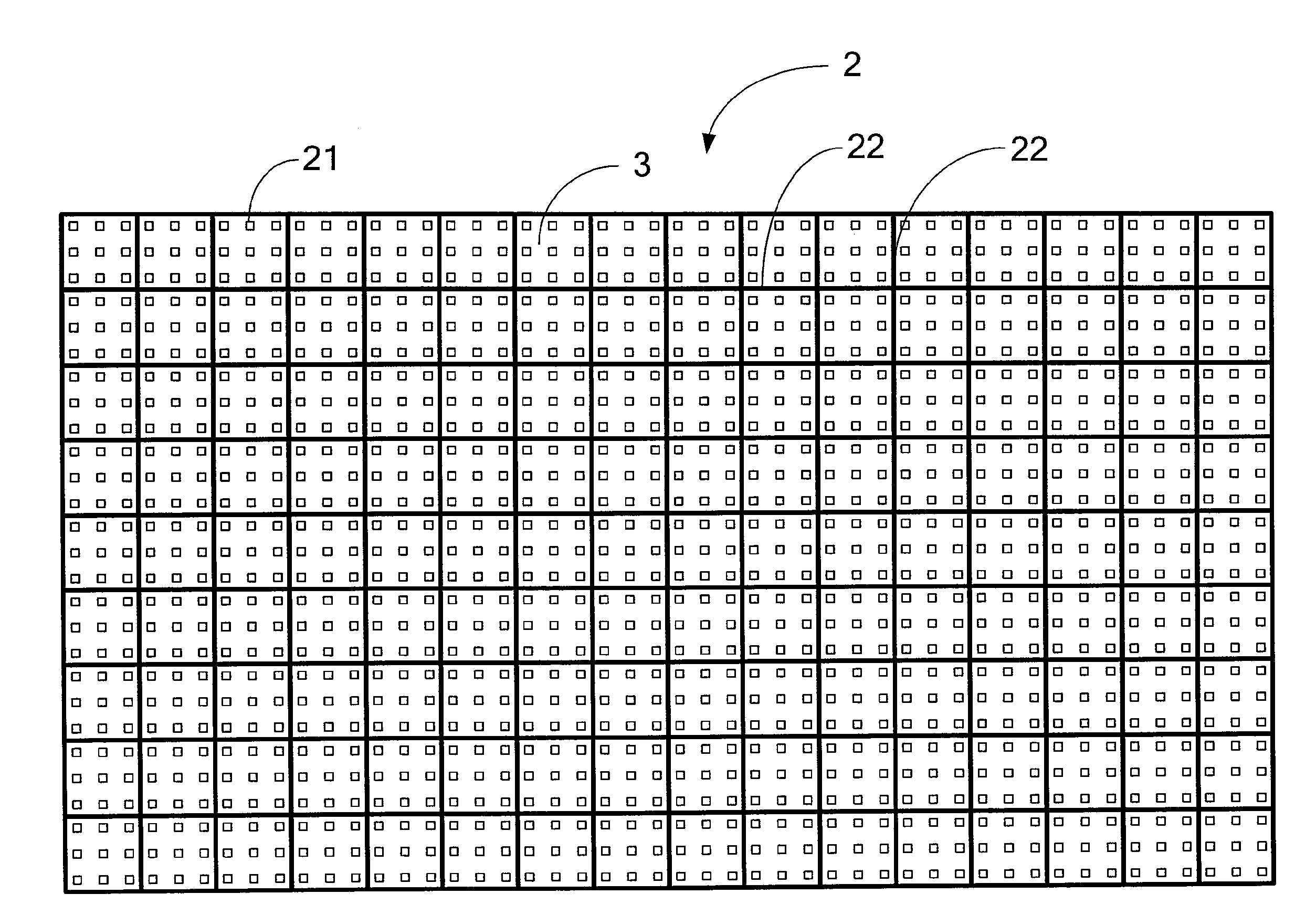
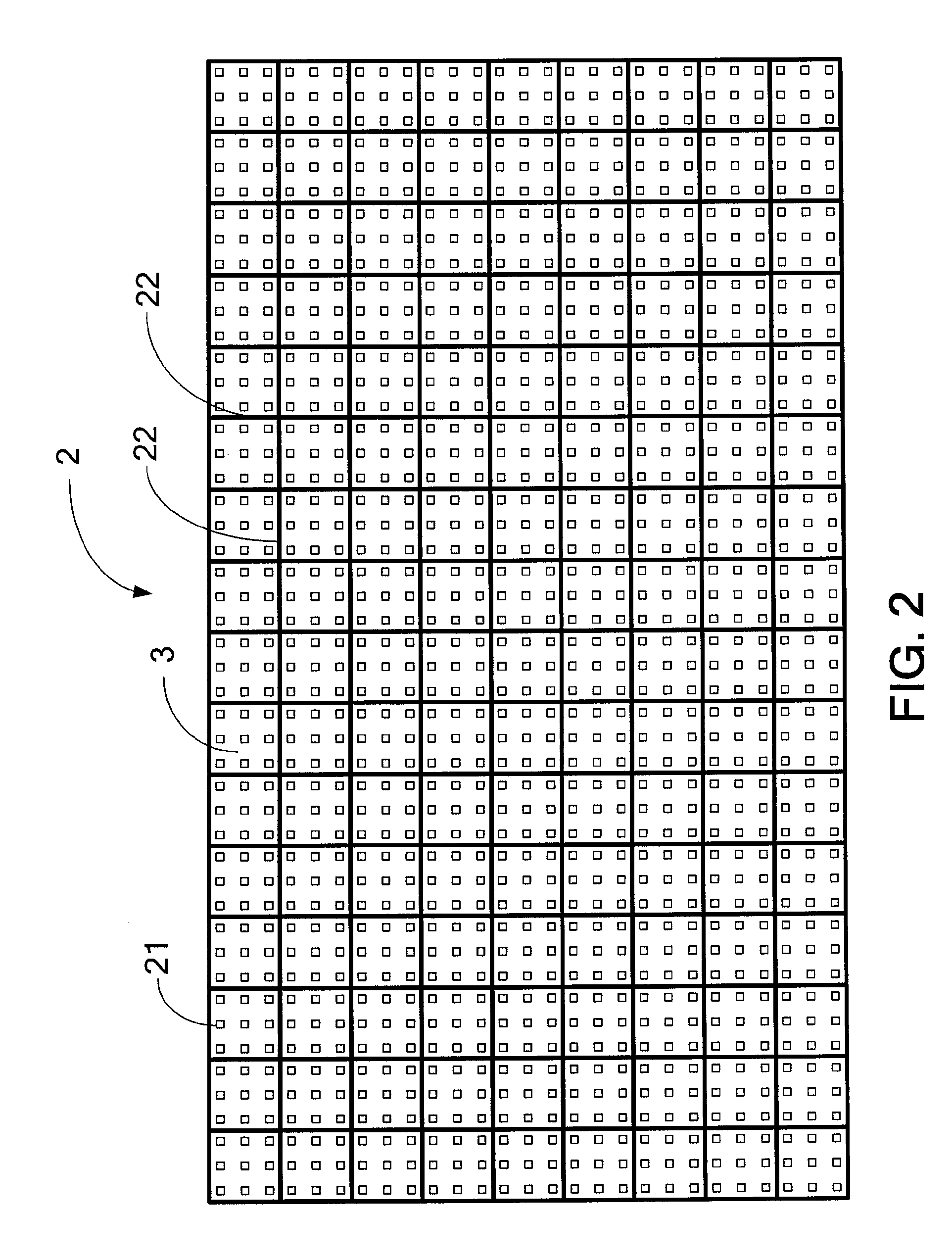
[0017]FIG. 2 depicts an embodiment of a backlight module 2 in accordance with this invention. As shown in FIG. 2, the backlight module 2, which is intended for use in LCDs or other purposes, comprises a plurality of backlight module units 3. These backlight module units 3 are arranged in an array, i.e., are sequentially disposed to form the backlight module 2. Each of the backlight module units 3 comprises a plurality of light sources 21 and a plurality of optical barriers 22, in which each of the backlight module units 3 is surrounded and defined by a number of optical barriers 22. However, due to the disposition of the optical barriers 22, the light rays emitted from the LEDs 21 will be reflected off the optical barrier 22 when impinging thereon. Consequently, these dark bands will degrade the image displaying quality on both sides of each optical barrier 22, especially at large viewing angles. For this reason, the distance between the plurality of light sources 21 and correspondi...


PUM


Abstract

A backlight module unit and a backlight module are provided. The backlight module unit includes a first light source, a second light source, and an optical barrier. A light source interval is defined between the first light source and the second light source, while a barrier interval is defined between the optical barrier and the second light source. Because the barrier interval is substantially shorter than a half of the light source interval, the backlight module unit mixes the light evenly, and prevents the dark bands from forming due to the disposition of the optical barrier. Thereby, the backlight module that comprises the plural aforesaid backlight units will have no dark bands, mix light evenly, and be thin overall.

Description

[0001]This application claims priority to Taiwan Patent Application No. 097102306 filed on Jan. 22, 2008, the disclosures of which are incorporated herein by reference in their entirety.CROSS-REFERENCES TO RELATED APPLICATIONS[0002]Not applicable.BACKGROUND OF THE INVENTION[0003]1. Field of the Invention[0004]The present invention relates to a backlight module unit of a backlight module, as well as the backlight module itself, and particularly relates to a backlight module unit having an appropriate interval between a light source and an optical barrier, as well as a backlight module comprising a plurality of such backlight module units.[0005]2. Descriptions of the Related Art[0006]As a result of technical developments, liquid crystal displays (LCDs) with low power consumption, low radiation, a light weight and slim profiles are widely used in various electronic products that require a screen, such as computers, mobile phones, televisions or the like. Compared to the conventional ca...

Claims


Application Information

Patent Timeline
IPC IPC(8): F21V1/00H05B33/00
CPCG02F1/133603G02F2001/133613G02F1/133611G02F1/133608G02F1/133613
Inventor PENG, CI-GUANGPENG, CHUNGCHEN, CHIH-KUANGLIU, PANG-HSUAN
Owner AU OPTRONICS CORP
Why Eureka
Try Eureka