Parallel inverter system

a technology of inverter system and inverter, which is applied in the direction of emergency power supply arrangement, process and machine control, instruments, etc., can solve the problems of lowering reliability, lowering reliability, and inability to parallel operation of inverter units, so as to increase frequency accuracy and frequency accuracy

Active Publication Date: 2009-07-23
SANYO DENKI CO LTD
View PDF6 Cites 16 Cited by
  • Summary
  • Abstract
  • Description
  • Claims
  • Application Information

AI Technical Summary

Benefits of technology

[0011]In order to allow the frequencies of the invert units to be consistent with each other as much as possible, in other words, to increase the frequency accuracy, a frequency difference detecting circuit may be provided to obtain a frequency from the detected voltage signal outputted from the voltage detector and detect a frequency difference between the obtained frequency and a frequency indicated with the commanded value for reference frequency. Further, the feedbac

Problems solved by technology

In a standalone operation of the inverter units where a synchronized signal is not given to each of the inverter units and each unit is operating independently from others, parallel operation of the inverter units is not possible if the reference sinusoidal signals used in the units are not synchronized due to an error in a crystal oscillation circuit which generates the reference sinusoidal signal.
In a parallel ope

Method used


Image

  • Parallel inverter system
  • Parallel inverter system
  • Parallel inverter system

Examples


Embodiment Construction

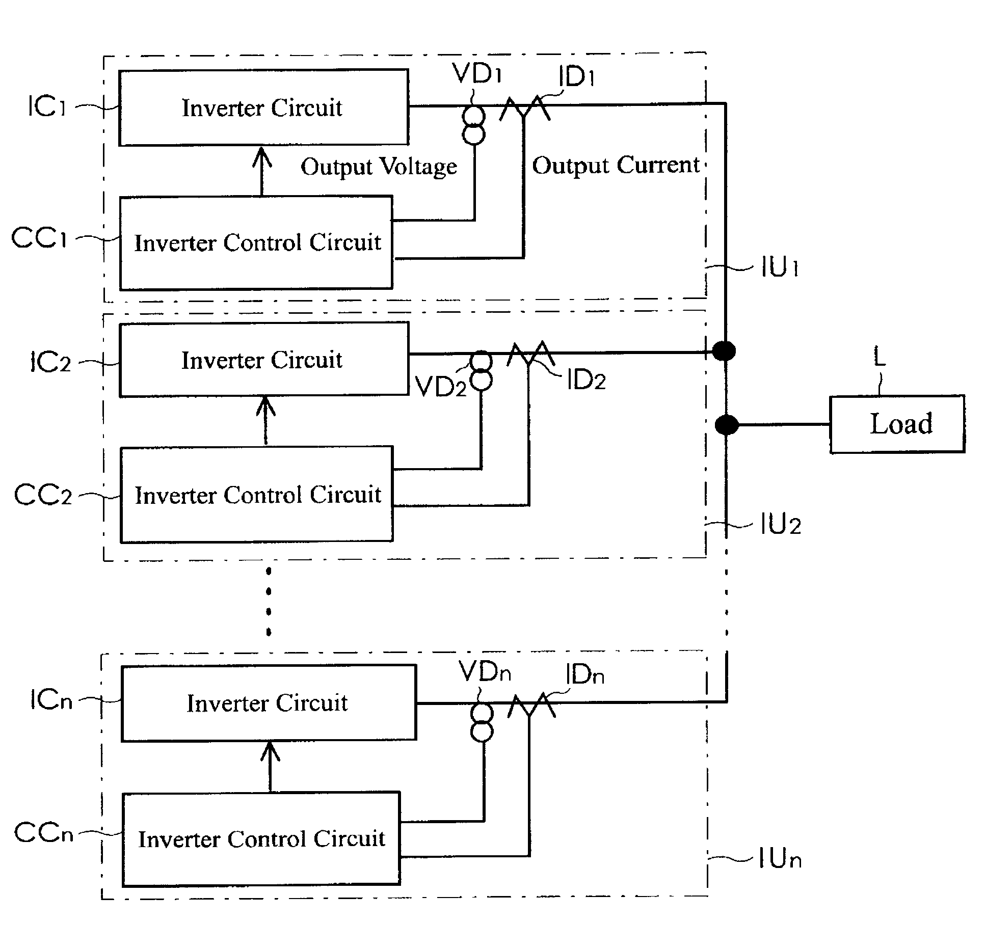
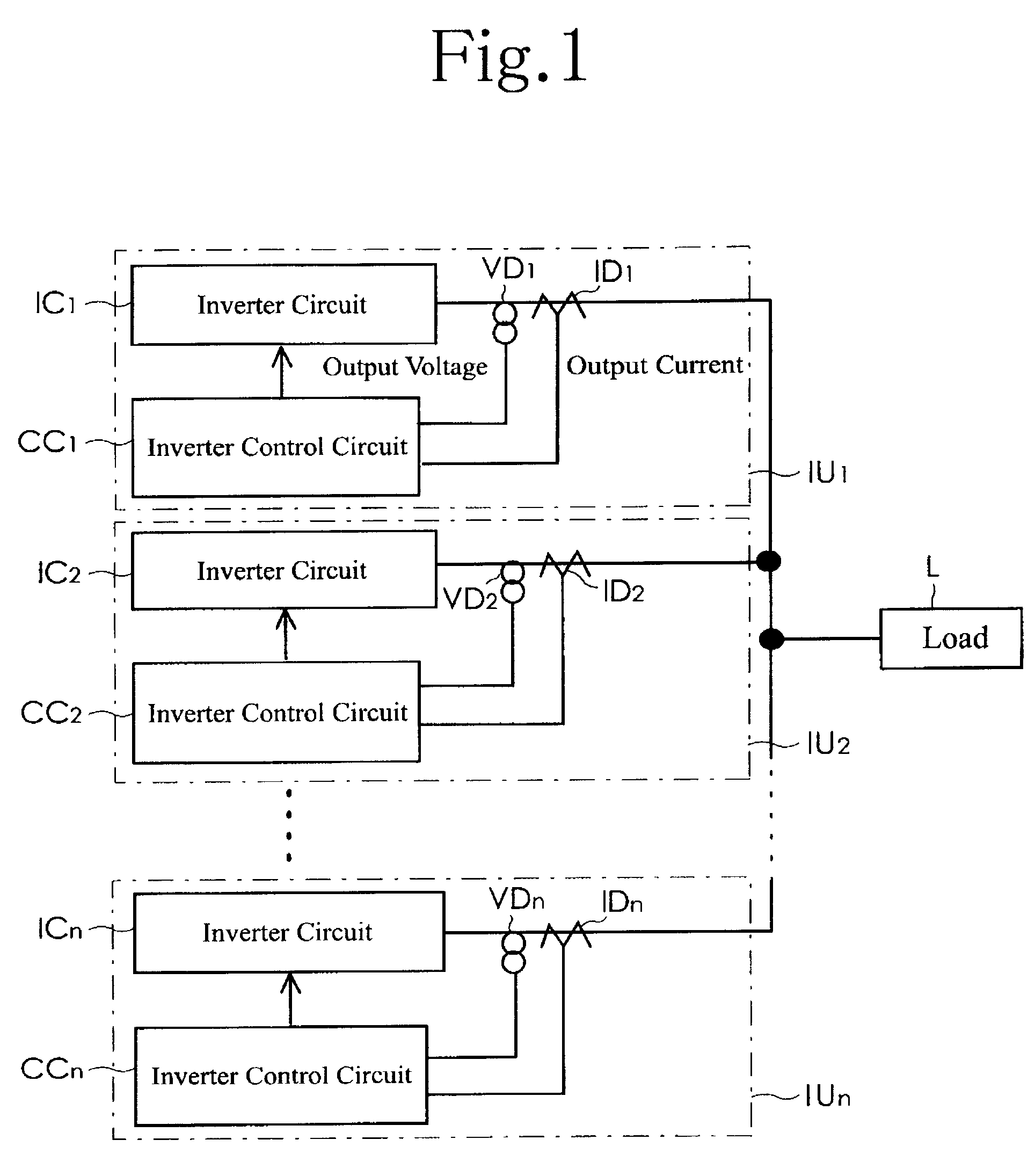
[0027]Embodiments of the present invention will now be described in detail with reference to accompanying drawings. FIG. 1 is a block diagram illustrating a basic configuration of a parallel inverter system according to the present invention. As illustrated in FIG. 1, the parallel inverter system includes a plurality of inverter units IU1 to IUn which are connected in parallel. The inverter units IU1 to IUn is operating independently from each other in substantially a synchronized condition, without transmitting and receiving a synchronized signal for synchronizing the inverter units. In a normal operation, as a principle, the inverter units IU1 to IUn operating in parallel or parallelly supply electric power to a load L at a distribution rate of substantially one-nth (1 / n). For example, if one inverter unit out of the inverter units IU1 to IUn is broken down, the remaining inverter units will supply electric power to the load with a varied distribution rate. Consequently, the inver...


PUM


Abstract

A parallel inverter system needs neither a dedicated line for synchronizing common portions nor switching operations, and includes a plurality of inverter units operating in parallel. An inverter control circuit of each inverter unit includes a sinusoidal signal generating circuit, a PWM control signal generating circuit, a phase difference circuit, a frequency difference circuit, and a feedback circuit. The feedback circuit inputs to the sinusoidal signal generating circuit an addition result value which is obtained by adding to a commanded value for reference frequency a value obtained from multiplication of a phase difference by a predetermined gain and a value obtained from multiplication of a frequency difference by a predetermined gain. The phase difference among outputs from the inverter units occurring in the parallel operation of the inverter units is reduced by changing the output frequencies of the inverter units. (140 word)

Description

FIELD OF THE INVENTION [0001]The present invention relates to a parallel inverter system including a plurality of inverter units which are connected in operation and operating in parallel or parallelly.BACKGROUND OF THE INVENTION [0002]Japanese Patent Publication No. 06-40704 (JP06-40704) discloses a technology relating to “a method of operating inverters in parallel.” The disclosed technology is directed to suppression of cross current flowing between the inverter units operating in parallel. The technology assumes that reference sinusoidal signals are substantially synchronized among the inverter units. In a standalone operation of the inverter units where a synchronized signal is not given to each of the inverter units and each unit is operating independently from others, parallel operation of the inverter units is not possible if the reference sinusoidal signals used in the units are not synchronized due to an error in a crystal oscillation circuit which generates the reference ...

Claims


Application Information

Patent Timeline
IPC IPC(8): H02M7/493
CPCH02M7/493
Inventor OKUI, YOSHIAKI
Owner SANYO DENKI CO LTD
Why Eureka
Try Eureka