

Optical multiplexer/demultiplexer
a multi-multi-channel optical resonator and optical multiplexer technology, applied in the field of optical multiplexers/demultiplexers, can solve the problem of difficult dense integration of a plurality of micro-ring optical resonators in lsi
- Summary
- Abstract
- Description
- Claims
- Application Information
AI Technical Summary
Benefits of technology
Problems solved by technology
Method used
Image

Examples
first embodiment
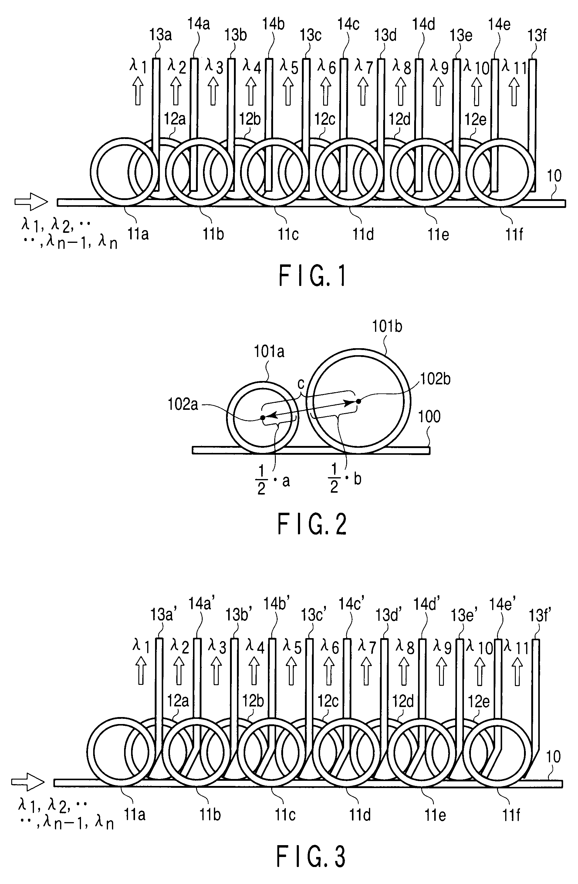
[0018]Before describing a first embodiment of the present invention in detail, the concept of the present embodiment is briefly described first.
[0019]In FIG. 2, 100 denotes a light guide main line for guiding lights of a plurality of wavelengths. 101a, 101b denote microring optical resonators optically coupled to the light guide main line 100, respectively. The microring optical resonators 101a, 101b are provided in a layer higher than a plane where the light guide main line 100 is disposed, and provided in the same layer (the level arrangement plane). 102a, 102b denote the central points of the microring optical resonators 101a, 101b, respectively. Further, in the drawing, ½·a is ½ of the outside diameter (ring diameter) “a” of a ring guide of the microring optical resonator 101a, ½·b is ½ of the outside diameter (ring diameter) “b” of a ring guide of the microring optical resonator 101b, and “c” is the distance (intercentral distance) between the central points 102a, 102b of the m...
second embodiment
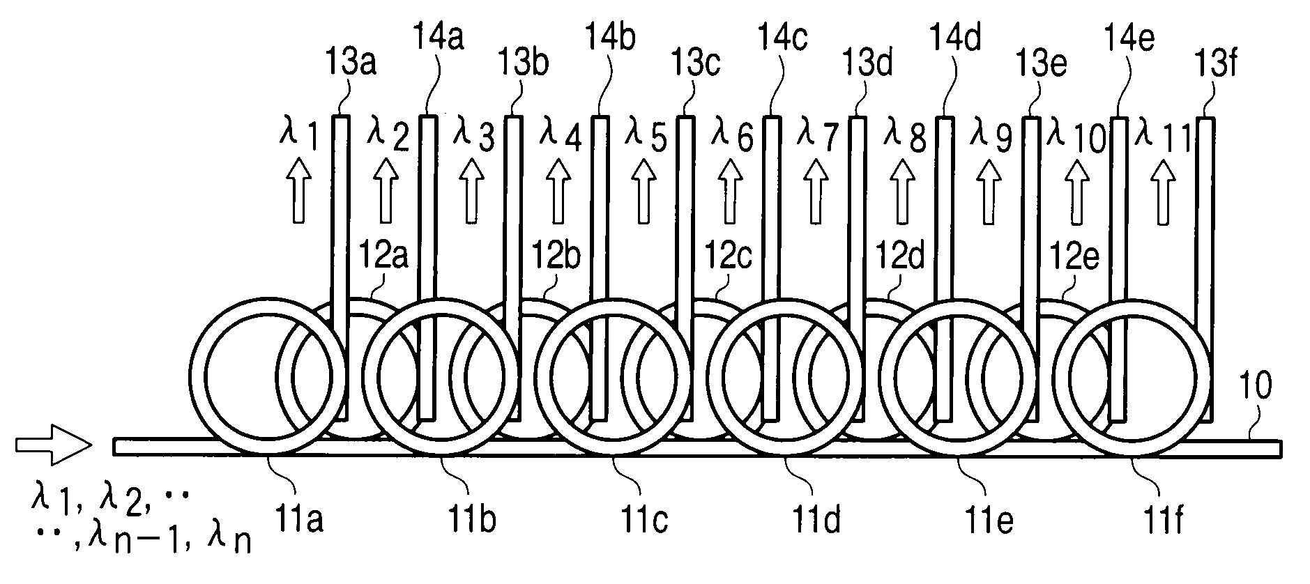
[0029]FIG. 3 shows an example of the configuration of an optical multiplexer / demultiplexer for performing wavelength multiplexing optical transmission in LSI, according to a second embodiment. In the example described in the present embodiment, the optical multiplexer / demultiplexer is used as a demultiplexer which selectively drops a light (guided light) of a single wavelength or lights of a plurality of wavelengths to light guide branch lines from a light guide main line. It is to be noted that the same numerals are assigned to the same parts as those in the optical multiplexer / demultiplexer (demultiplexer) shown in FIG. 1 and a detailed description is omitted.
[0030]In the optical multiplexer / demultiplexer shown in the first embodiment (see FIG. 1), it is desirable that the light guide branch lines 13a to 13f, 14a to 14e optically coupled to the light guide main line 10 via the microring optical resonators 11a to 11f, 12a to 12e be arranged to perpendicularly intersect the tangenti...
third embodiment
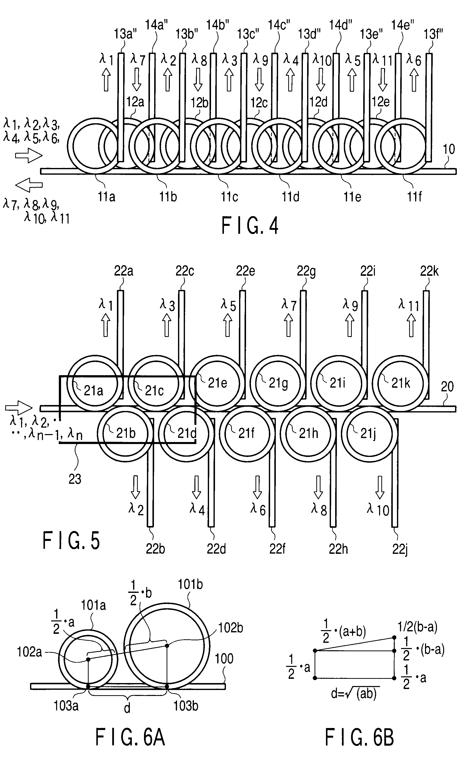
[0044]Before describing a third embodiment of the present invention in detail, the concept of the present embodiment is briefly described first.
[0045]In FIG. 6A, 100 denotes a light guide main line. 101a, 101b denote microring optical resonators optically coupled to the light guide main line 100, respectively. 102a, 102b denote the central points of the microring optical resonators 101a, 101b, respectively. 103a, 103b denote points on the central line of the light guide main line 100 which minimize the distance between the light guide main line 100 and the outer periphery of each of the microring optical resonators 101a, 101b (each microring optical resonator has two such points as shown in FIG. 7, so that a central point between these two points is 103a, 103b). Further, in the drawing, ½·a is ½ of the outside diameter (ring diameter) “a” of a ring guide of the microring optical resonator 101a, ½·b is ½ of the outside diameter “b” of a ring guide of the microring optical resonator 1...
PUM
 Abstract
Description
Claims
Application Information