Fuel pump

a fuel pump and pump body technology, applied in the direction of fuel injecting pumps, machines/engines, positive displacement liquid engines, etc., can solve the problems of increasing the product cost and increasing the product cost of the fuel pump, and achieve the effect of reducing the pressure pulsation of the two metal diaphragms

Active Publication Date: 2009-07-23
DENSO CORP
View PDF16 Cites 37 Cited by
  • Summary
  • Abstract
  • Description
  • Claims
  • Application Information

AI Technical Summary

Benefits of technology

[0009]In view of the foregoing problems, it is an object of the present invention to provide a fuel pump having a diaphragm device with two metal diaphragms, in which the reduction effect of the pressure pulsation of the two metal diaphragms can be effectively obtained even when the frequency of the pressure pulsation is changed.
[0010]It is another object of the present invention to provide a fuel pump having a diaphragm device with two metal diaphragms, in which the reduction effect of the pressure pulsation of the two metal diaphragms can be effectively obtained without increasing the product cost, even when the frequency of the pressure pulsation is changed.
[0012]Because the mass addition member is attached to the inside surface of at least one of the first and second diaphragms, it is possible for the first and second diaphragms with the mass addition member to have different characteristic frequencies. Accordingly, when the pulsation frequency of pressure pulsation of the fuel in the suction chamber is different from both the first and second diaphragms in a case where the fuel pressure is increased, both the first and second diaphragms are deformed inside, so as to increase the volume of the suction passage and reduce the pressure pulsation. When the pulsation frequency of pressure pulsation of the fuel in the suction chamber becomes equal to any one of the first and second diaphragms, the other one of the first and second diaphragms does not resonate thereby having the reduction effect of the pressure pulsation. As a result, even when the pulsation frequency of the pressure pulsation of the fuel in the suction chamber is changed, the reduction effect of the pressure pulsation of the fuel can be effectively obtained by the diaphragm device. In the diaphragm device, by changing the weight of the mass addition member, a difference between the characteristic frequencies of the first and second diaphragms with the mass addition member can be easily set, In addition, when the first and second diaphragms have the same shape in cross section, the size increase and the cost increase in the fuel pump can be restricted.
[0013]For example, the mass addition member is made of a material having flexibility more than a predetermined degree. Generally, the predetermined degree of the flexibility in the mass addition member is set such that a deformation (spring characteristic) of the first and second diaphragms is not restricted by the mass addition member. Therefore, even when the mass addition member is attached to the first and second diaphragms, the reduction effect of the pressure pulsation of the fuel can be effectively obtained by the diaphragm device.
[0017]Accordingly, even when the pulsation frequency of pressure pulsation of the fuel in the suction chamber becomes equal to any one of the first and second diaphragms, the other one of the first and second diaphragms does not resonate thereby having the reduction effect of the pressure pulsation. As a result, even when the pulsation frequency of the pressure pulsation of the fuel in the suction chamber is changed, the reduction effect of the pressure pulsation of the fuel can be effectively obtained by the diaphragm device. In the diaphragm device, a difference between the characteristic frequencies of the first and second diaphragms can be easily set.
[0019]According to another aspect of the present invention, a fuel pump includes: a housing having therein a suction passage through which fuel is drawn and a pressurization chamber into which the fuel from the suction passage flows; a plunger held in the housing to be reciprocable so as to pressurize the fuel flowing into the pressurization chamber; and a diaphragm device located in a suction chamber that is provided in the suction passage. The diaphragm device includes a pair of first and second diaphragms that are arranged to define an inner space therebetween and are air-tightly sealed at its entire peripheries, and the first and second diaphragms generally have different thicknesses in cross section while having the same outer shape. Accordingly, the first and second diaphragms can be easily configured to have, respectively, characteristic frequencies which are different from each other by only setting the thicknesses of the first and second diaphragms different from each other. As a result, the reduction effect of the pressure pulsation of the fuel can be effectively obtained by the diaphragm device while the production cost of the diaphragm device can be reduced.

Problems solved by technology

However, because the two metal diaphragms having different uneven shapes in cross section are provided in the diaphragm device of the fuel pump, the product cost of the fuel pump is increased.
Therefore, it is necessary to prepare various kinds of the uneven metal diaphragms in accordance with the engine type and the vehicle type, thereby more increasing the product cost.

Method used


Image

  • Fuel pump
  • Fuel pump
  • Fuel pump

Examples


first embodiment

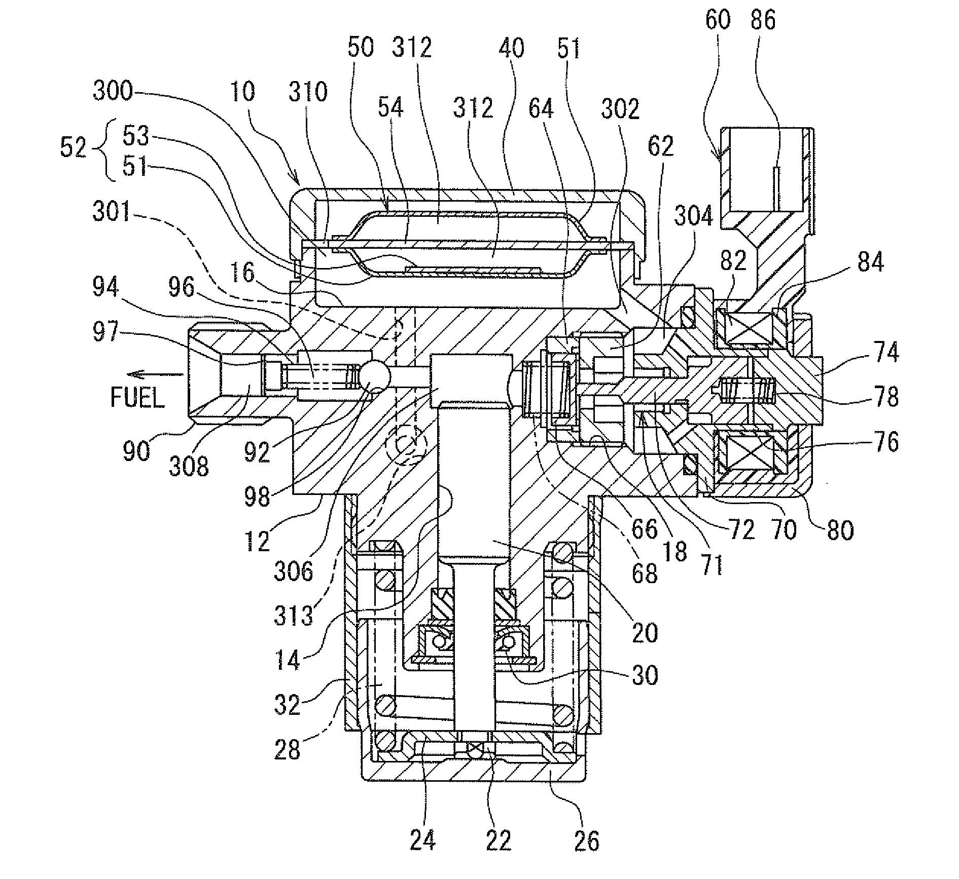
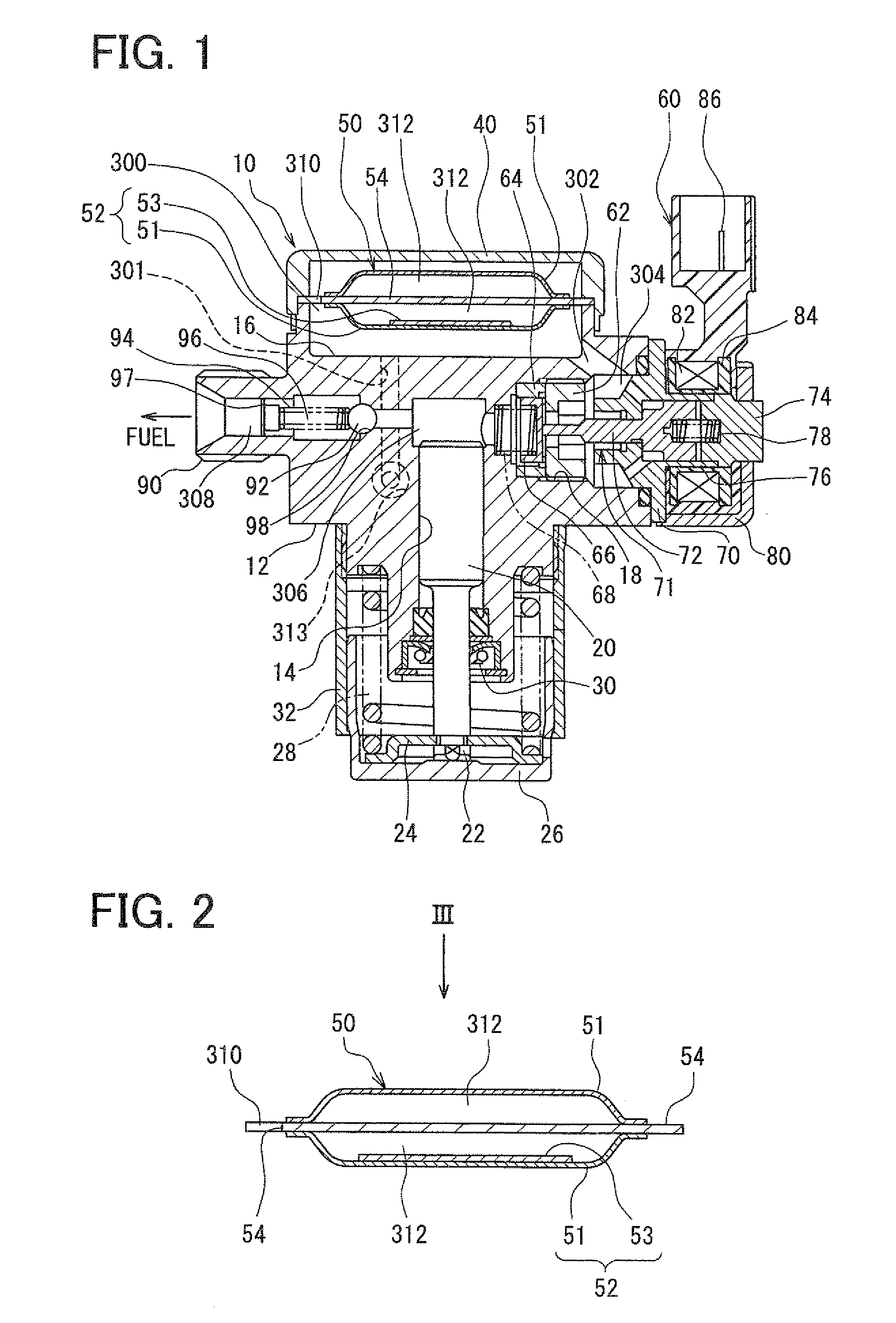
[0037]FIG. 1 shows an example of a high-pressure fuel pump 10 according to a first embodiment of the present invention. The fuel pump 10 is a fuel supply pump configured to supply fuel to an injector of a diesel engine or a gasoline engine, for example. The fuel pump 10 has a fuel passage portion from a fuel inlet (not shown) to a discharge portion 90 that is used as a fuel outlet. The fuel passage portion from the fuel inlet to the discharge portion 90 includes a suction chamber 300, a fuel communication passage 302, a fuel gallery 304, a pressurization chamber 306 and a discharge passage 308. A suction passage for drawing the fuel into the pressurization chamber 306 includes the suction chamber 300, the fuel passage 302 and the fuel gallery 304.

[0038]The housing body 12 is formed integrally by using an iron material such as martensitic stainless steel, for example. The housing body 12 is configured to have a cover 40 and a pump housing of the fuel pump 10. The cover 40 is fitted t...

second embodiment

[0077]FIG. 7 shows a pulsation damper 150 (diaphragm device) for a fuel pump 10 according to a second embodiment of the present invention.

[0078]As shown in FIG. 7, in the pulsation damper 150 of the second embodiment, the structure of the mass addition member attached to one of a pair of diaphragms (151, 151) is changed as compared with the pulsation damper 50 described in the above first embodiment. For example, the mass addition member bonded to an inner surface of the diaphragm 151 is constructed with a flexible metal plate 153 and a bonding material 156 (adhesive) having a suitable flexibility more than a predetermined degree. Next, the structure of the pulsation damper 150 of the fuel pump 10 according to the second embodiment will be described.

[0079]The pulsation damper 150 includes two diaphragms 151 and 152, and a plate 154 inserted between the two diaphragms 151 and 152. The bonding structure of the plate 154 between the two diaphragms 151 and 152 is similar to that in the ...

third embodiment

[0086]FIG. 9 shows a pulsation damper 250 (diaphragm device) for a fuel pump 10 according to a third embodiment of the present invention.

[0087]In the above-described first embodiment, a mass addition member is attached to any one of the two diaphragms. However, in the third embodiment, mass addition members are attached to two diaphragms, respectively. In the third embodiment, the other structure of the fuel pump 10 is similar to that of the fuel pump 10 of the above-described first embodiment. Next, the structure of the pulsation damper 250 of the fuel pump 10 according to the third embodiment will be described.

[0088]The pulsation damper 250 includes a diaphragm 251, a diaphragm 252, and a plate 254 inserted between the two diaphragms 251 and 252. The bonding structure of the plate 254 between the two diaphragms 251 and 252 is similar to that of the plate 54 in the pulsation damper 50 of the above-described first embodiment. The plate 254 has a shape similar to that of the plate 54...


PUM


Abstract

A fuel pump includes a housing having therein a suction passage and a pressurization chamber into which fuel from the suction passage flows, a plunger held in the housing to be reciprocable so as to pressurize the fuel flowing into the pressurization chamber, and a diaphragm device located in a suction chamber that is provided in the suction passage. The diaphragm device includes a pair of first and second diaphragms that are arranged to define an inner space therebetween and air-tightly sealed at its entire peripheries. A mass addition member may be attached to an inside surface of at least one of the first and second diaphragms, so that the first and second diaphragms with the mass addition member have different characteristic frequencies. Accordingly, pressure pulsation of the fuel in the suction chamber can be effectively reduced by the pulsation damper.

Description

CROSS REFERENCE TO RELATED APPLICATION[0001]This application is based on Japanese Patent Application No. 2008-011971 filed on Jan. 22, 2008, the contents of which are incorporated herein by reference in its entirety.FIELD OF THE INVENTION[0002]The present invention relates to a fuel pump for pressurizing and sending fuel. More particularly, the present invention relates to a damper device provided in the fuel pump.BACKGROUND OF THE INVENTION[0003]In a fuel pump described in JP-A-2000-193186 (corresponding to U.S. Pat. No. 6,053,208), fuel drawn into a pressurization chamber is pressurized and discharged by using a plunger that is held to be reciprocable in a cylinder of a housing.[0004]In the fuel pump, a single plate metal diaphragm is located in a suction passage connected to the pressurization chamber, and is used as a damper mechanism for reducing a pressure pulsation of the fuel drawn from the suction passage to the pressurization chamber. When the pressure pulsation of the fue...

Claims


Application Information

Patent Timeline
Patent Type & Authority Applications(United States)
IPC IPC(8): F04B11/00
CPCF02M55/04F04B43/067F02M63/0265F02M59/02
Inventor INOUE, HIROSHIOGURI, TATSUMI
Owner DENSO CORP
Why Eureka
Try Eureka