Fuel pump
a fuel pump and pump body technology, applied in the direction of fuel injecting pumps, machines/engines, positive displacement liquid engines, etc., can solve the problems of size increase and cost increase in the fuel pump, and achieve the effect of reducing the pressure pulsation effect of the two metal diaphragms
- Summary
- Abstract
- Description
- Claims
- Application Information
AI Technical Summary
Benefits of technology
Problems solved by technology
Method used
Image
Examples
first embodiment
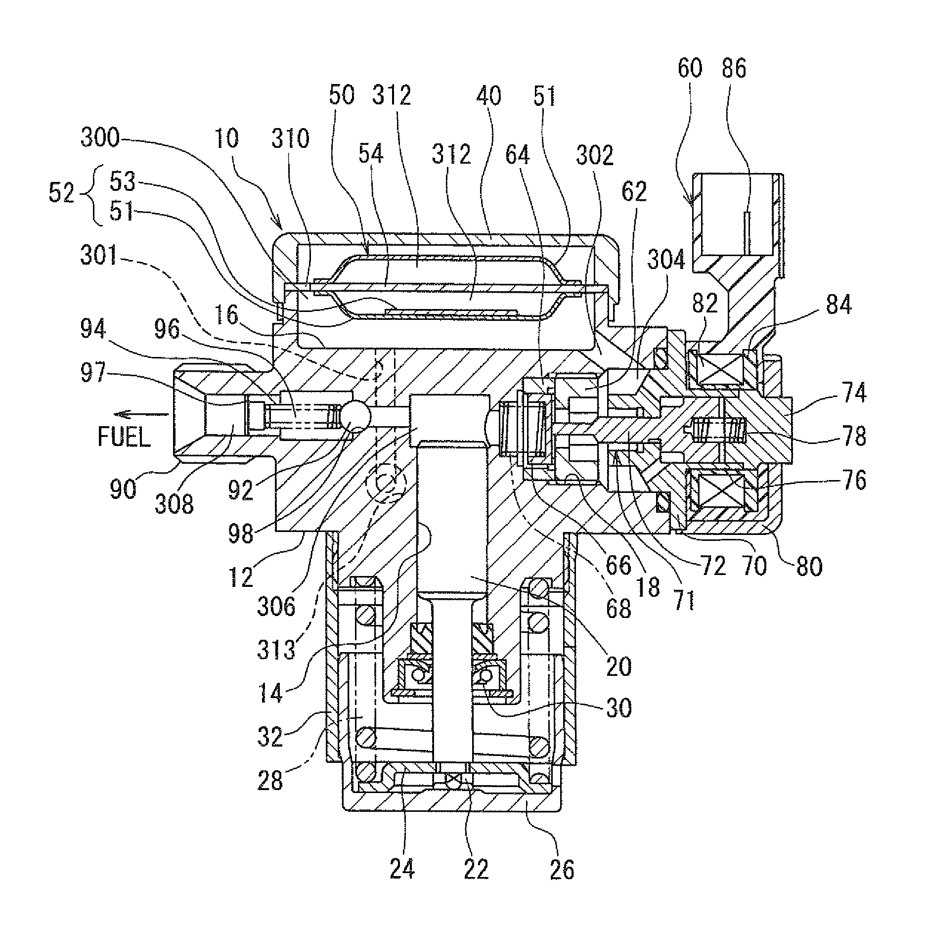
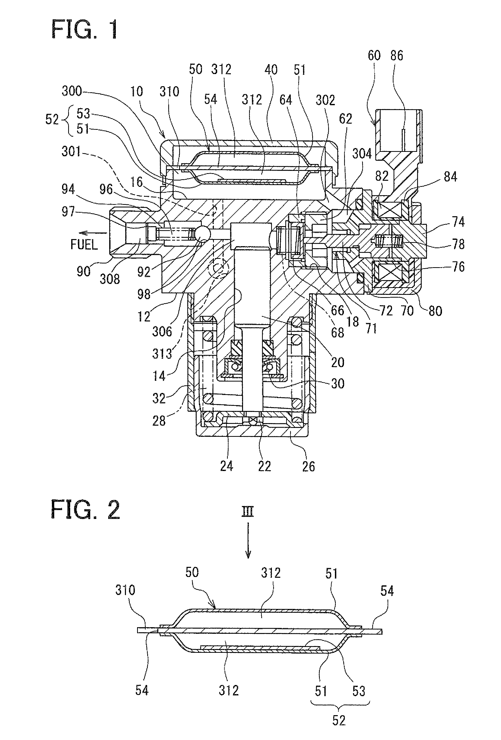
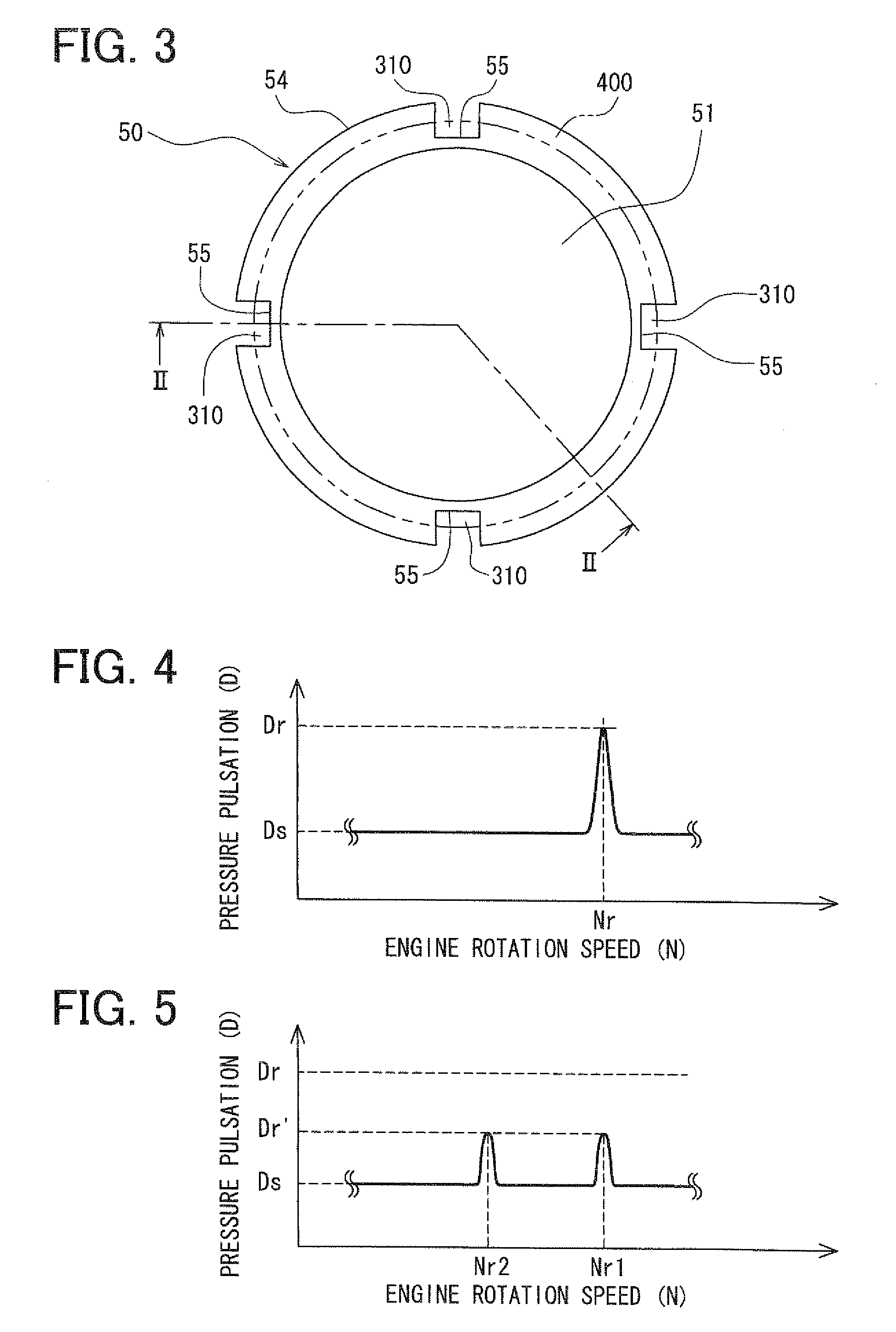
[0037]FIG. 1 shows an example of a high-pressure fuel pump 10 according to a first embodiment of the present invention. The fuel pump 10 is a fuel supply pump configured to supply fuel to an injector of a diesel engine or a gasoline engine, for example. The fuel pump 10 has a fuel passage portion from a fuel inlet (not shown) to a discharge portion 90 that is used as a fuel outlet. The fuel passage portion from the fuel inlet to the discharge portion 90 includes a suction chamber 300, a fuel communication passage 302, a fuel gallery 304, a pressurization chamber 306 and a discharge passage 308. A suction passage for drawing the fuel into the pressurization chamber 306 includes the suction chamber 300, the fuel passage 302 and the fuel gallery 304.
[0038]The housing body 12 is formed integrally by using an iron material such as martensitic stainless steel, for example. The housing body 12 is configured to have a cover 40 and a pump housing of the fuel pump 10. The cover 40 is fitted t...
second embodiment
[0077]FIG. 7 shows a pulsation damper 150 (diaphragm device) for a fuel pump 10 according to a second embodiment of the present invention.
[0078]As shown in FIG. 7, in the pulsation damper 150 of the second embodiment, the structure of the mass addition member attached to one of a pair of diaphragms (151, 151) is changed as compared with the pulsation damper 50 described in the above first embodiment. For example, the mass addition member bonded to an inner surface of the diaphragm 151 is constructed with a flexible metal plate 153 and a bonding material 156 (adhesive) having a suitable flexibility more than a predetermined degree. Next, the structure of the pulsation damper 150 of the fuel pump 10 according to the second embodiment will be described.
[0079]The pulsation damper 150 includes two diaphragms 151 and 152, and a plate 154 inserted between the two diaphragms 151 and 152. The bonding structure of the plate 154 between the two diaphragms 151 and 152 is similar to that in the ...
third embodiment
[0086]FIG. 9 shows a pulsation damper 250 (diaphragm device) for a fuel pump 10 according to a third embodiment of the present invention.
[0087]In the above-described first embodiment, a mass addition member is attached to any one of the two diaphragms. However, in the third embodiment, mass addition members are attached to two diaphragms, respectively. In the third embodiment, the other structure of the fuel pump 10 is similar to that of the fuel pump 10 of the above-described first embodiment. Next, the structure of the pulsation damper 250 of the fuel pump 10 according to the third embodiment will be described.
[0088]The pulsation damper 250 includes a diaphragm 251, a diaphragm 252, and a plate 254 inserted between the two diaphragms 251 and 252. The bonding structure of the plate 254 between the two diaphragms 251 and 252 is similar to that of the plate 54 in the pulsation damper 50 of the above-described first embodiment. The plate 254 has a shape similar to that of the plate 54...
PUM
 Abstract
Description
Claims
Application Information
 - R&D
- Intellectual Property
- Life Sciences
- Materials
- Tech Scout
- Unparalleled Data Quality
- Higher Quality Content
- 60% Fewer Hallucinations
Browse by: Latest US Patents, China's latest patents, Technical Efficacy Thesaurus, Application Domain, Technology Topic, Popular Technical Reports.
© 2025 PatSnap. All rights reserved.Legal|Privacy policy|Modern Slavery Act Transparency Statement|Sitemap|About US| Contact US: help@patsnap.com


