Piston pump

Inactive Publication Date: 2009-07-23
ROBERT BOSCH GMBH
View PDF8 Cites 3 Cited by
  • Summary
  • Abstract
  • Description
  • Claims
  • Application Information

AI Technical Summary

Problems solved by technology

However, this requires metal-cutting machining of the piston, which is very complicated.
It has furthermore been found that because of the delivery by the piston and the attendant

Method used


Image

  • Piston pump
  • Piston pump
  • Piston pump

Examples


Embodiment Construction

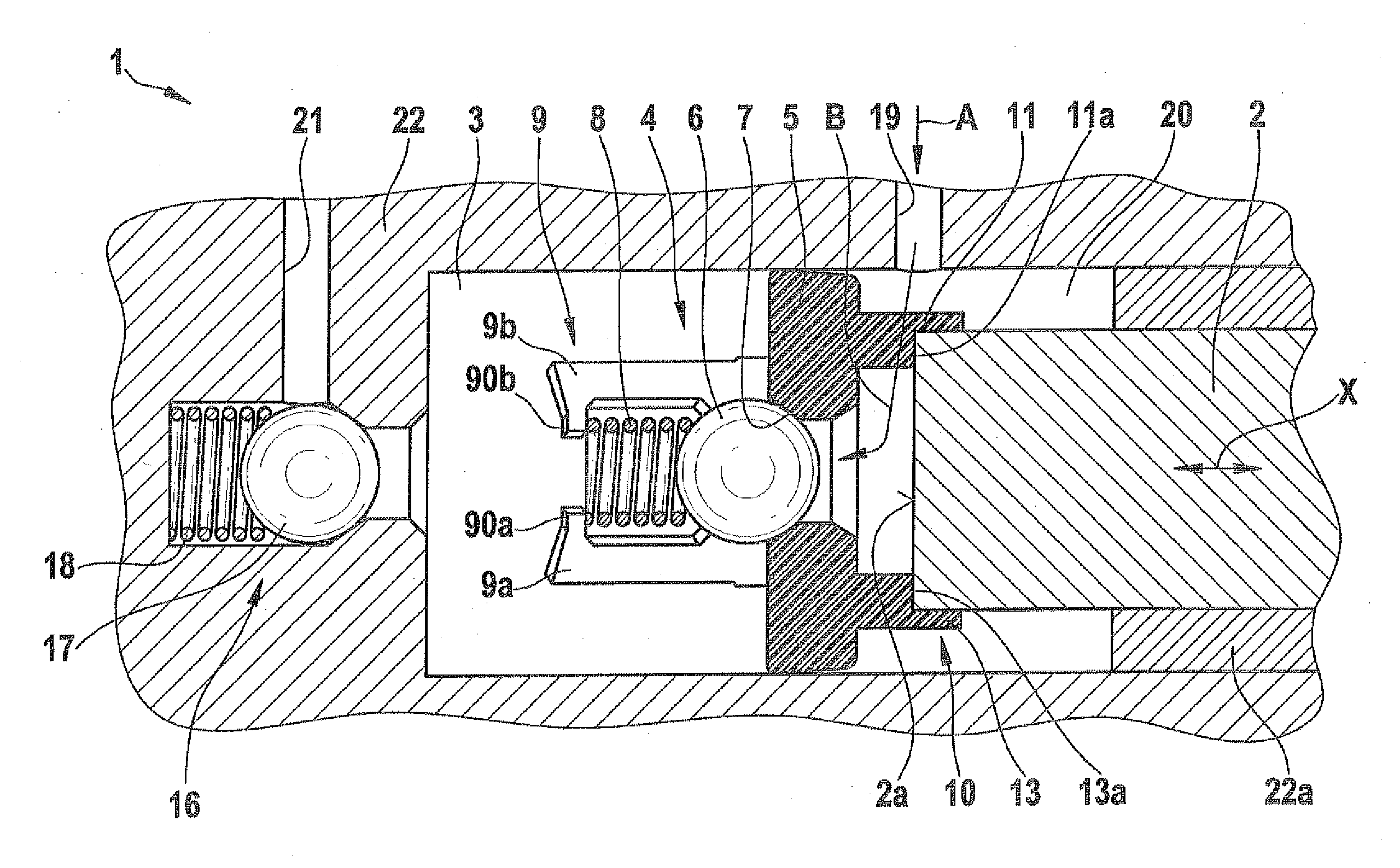
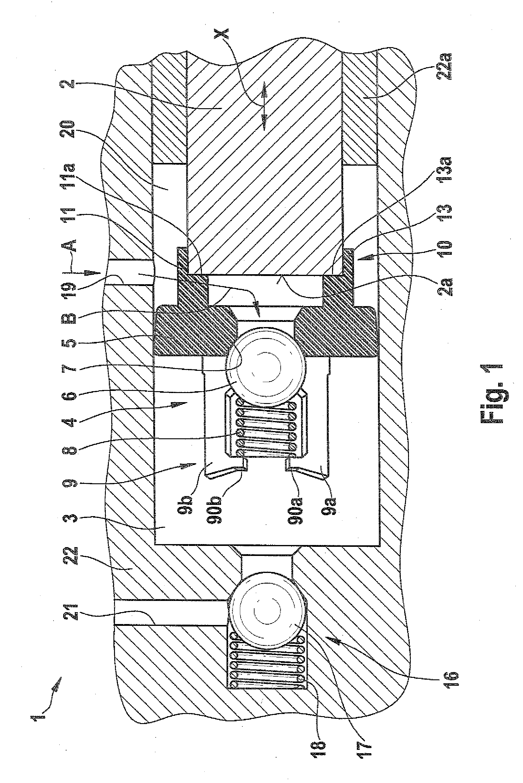
[0022]A piston pump 1 in a first exemplary embodiment of the invention will be described below with reference to FIGS. 1 through 5.

[0023]As can be seen from FIG. 1, the piston pump 1 includes a piston 2, which is made from a solid material as a cylindrical roll. The piston 2 is guided movably back and forth (double arrow X in FIG. 1) on a housing 22 in a sleeve 22a and is driven for instance by means of a cam. The piston pump 1 furthermore includes an inlet valve 4, an outlet valve 16, and a pressure chamber 3 disposed between the inlet valve 4 and the outlet valve 16.

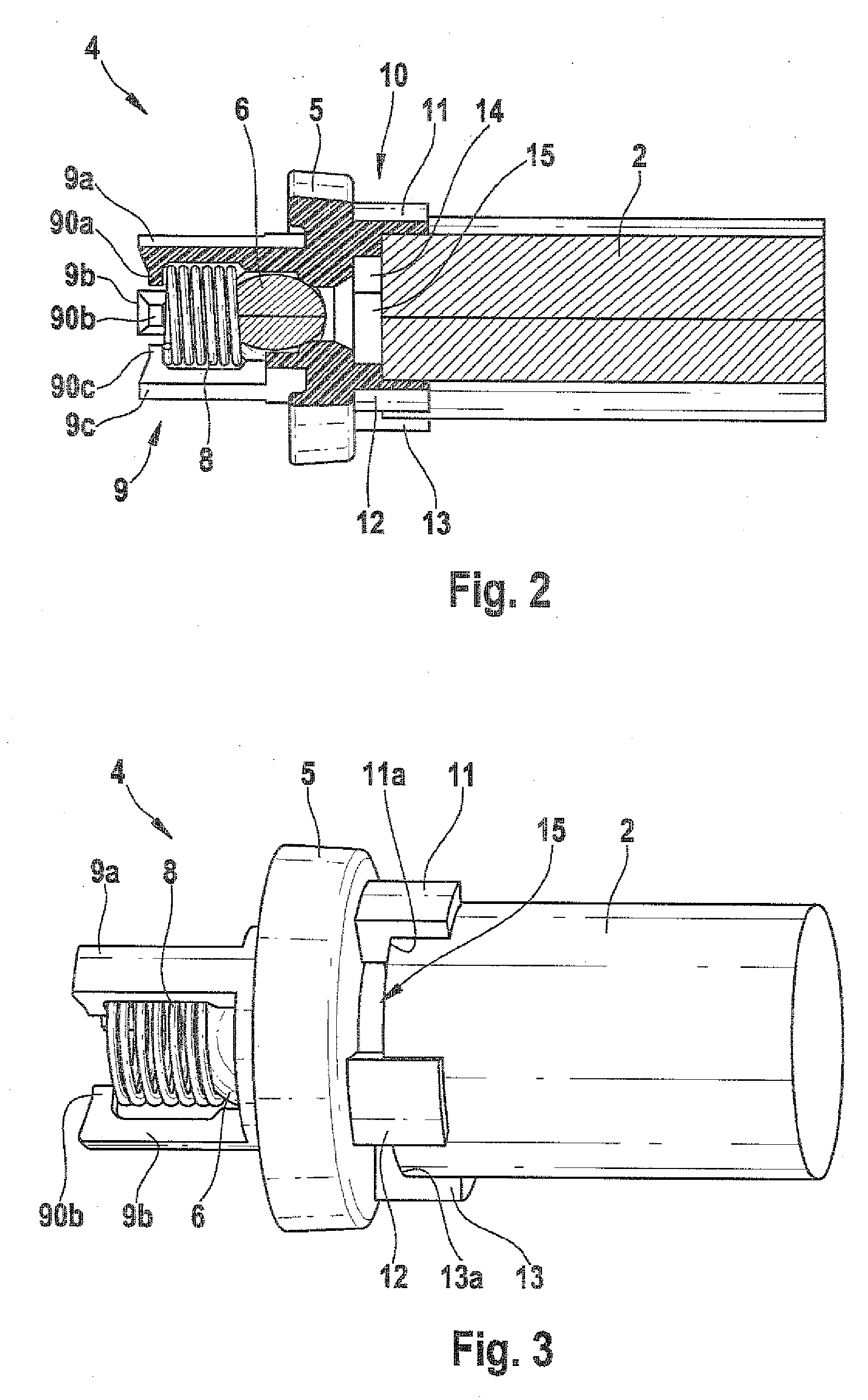
[0024]The inlet valve 4 includes a valve body 5, which is made from a plastic material. The inlet valve 4 furthermore includes a closing element 6, which in this exemplary embodiment is a ball. The closing element 6 either seals off a valve seat 7 that is formed on the valve body 5 or opens the valve seat. The closing element 6 is prestressed against the valve seat 7 by means of a cylindrical spring 8. The cylindrical ...


PUM


Abstract

The invention relates to a piston pump for conveying fluids. The piston pump includes a piston, and a pressure chamber located between an intake valve and a discharge valve. The intake valve is arranged between the pressure chamber and a low-pressure zone of the piston pump. The intake valve has a valve body, a closing element, a device for preloading the closing element, and a device for fastening the intake valve to the piston. The fastening device encompasses at least two fastening elements which protrude from the valve body toward the piston. The fastening elements are positioned at a distance from one another, and are fitted with inlets therebetween for supplying fluid. The invention further relates to a piston pump having an intake valve without a spring-biased element.

Description

PRIOR ART[0001]The present invention relates to a piston pump for conveying fluids, and in particular to a piston pump for conveying liquids in vehicles, such as brake fluid or fuel.[0002]Piston pumps in various embodiments are known from the prior art. In vehicles, piston pumps are used for instance as fuel pumps, or as pumps for supplying pressure to brake systems. A known piston pump, between an inlet valve and an outlet valve, has a work or pressure chamber, in which a pressure is built up by means of a linear motion of a piston. In order to have the most compact possible construction, the fluid is delivered to the inlet valve through a plurality of radial bores and a longitudinal bore in the piston. However, this requires metal-cutting machining of the piston, which is very complicated. It has furthermore been found that because of the delivery by the piston and the attendant relatively long travel distances for delivering the fluid, flow losses occur. Hence the known piston pu...

Claims


Application Information

Patent Timeline
IPC IPC(8): F04B53/10
CPCB60T8/4031F04B53/126F04B1/0452F04B1/04F04B53/12
Inventor BOLLWERK, ANDRESCHULLER, WOLFGANGBELING, HORSTWAGNER, JUERGENSCHUESSLER, MICHAELHALLERMANN, STEFAN
Owner ROBERT BOSCH GMBH
Why Eureka
Try Eureka