Method and system for detecting stack alteration

a stack alteration and stack technology, applied in the direction of program control, computation using denominational number representation, instruments, etc., can solve the problems of arbitrary code injection, buffer overflow, integer overflow, format string error,

a stack alteration and stack technology, applied in the direction of program control, computation using denominational number representation, instruments, etc., can solve the problems of arbitrary code injection, buffer overflow, integer overflow, format string error,

US20090187748A1Inactive Publication Date: 2009-07-23AVAGO TECH WIRELESS IP SINGAPORE PTE

Image

  • Method and system for detecting stack alteration
  • Method and system for detecting stack alteration
  • Method and system for detecting stack alteration

Examples


Embodiment Construction

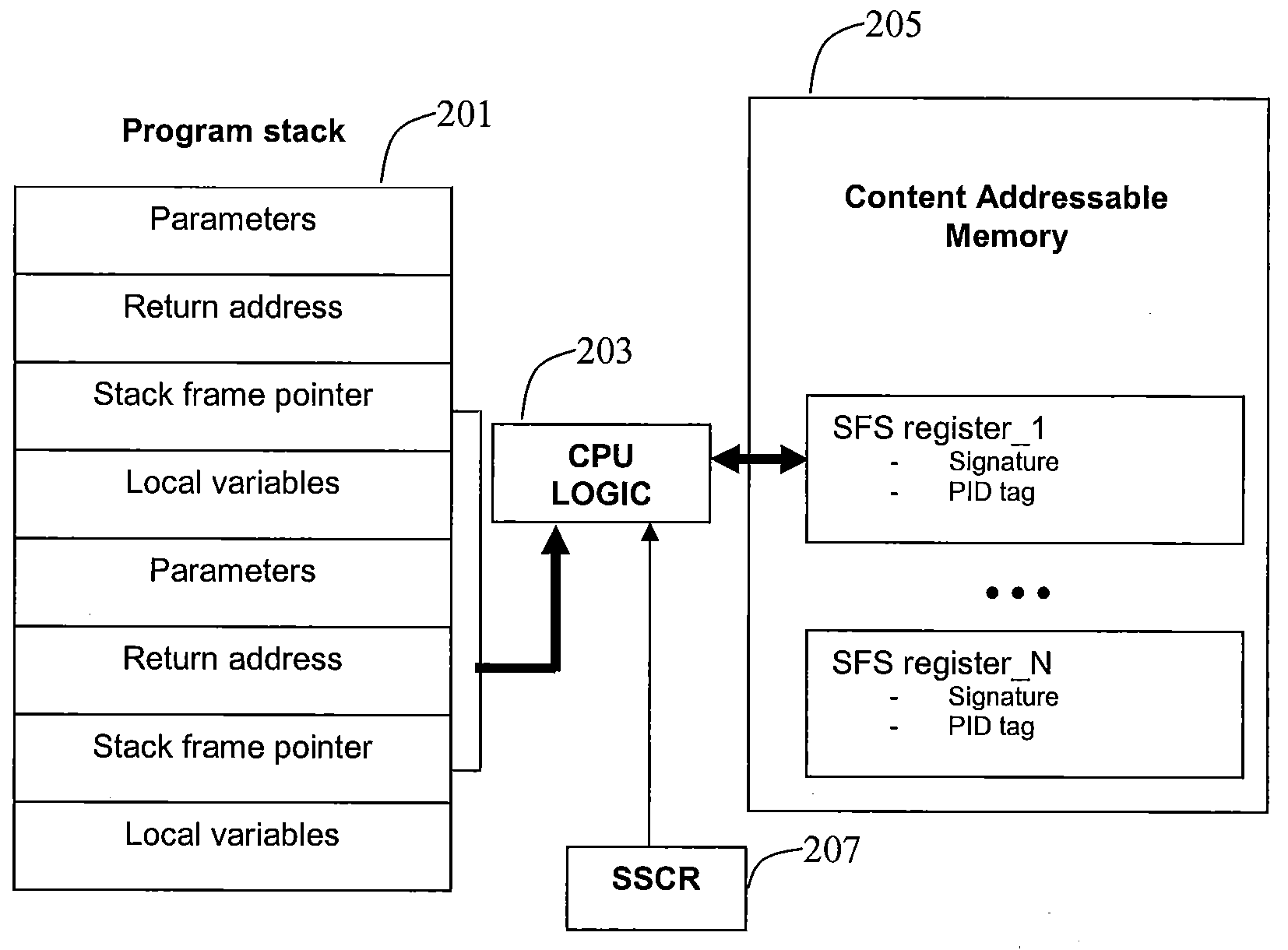
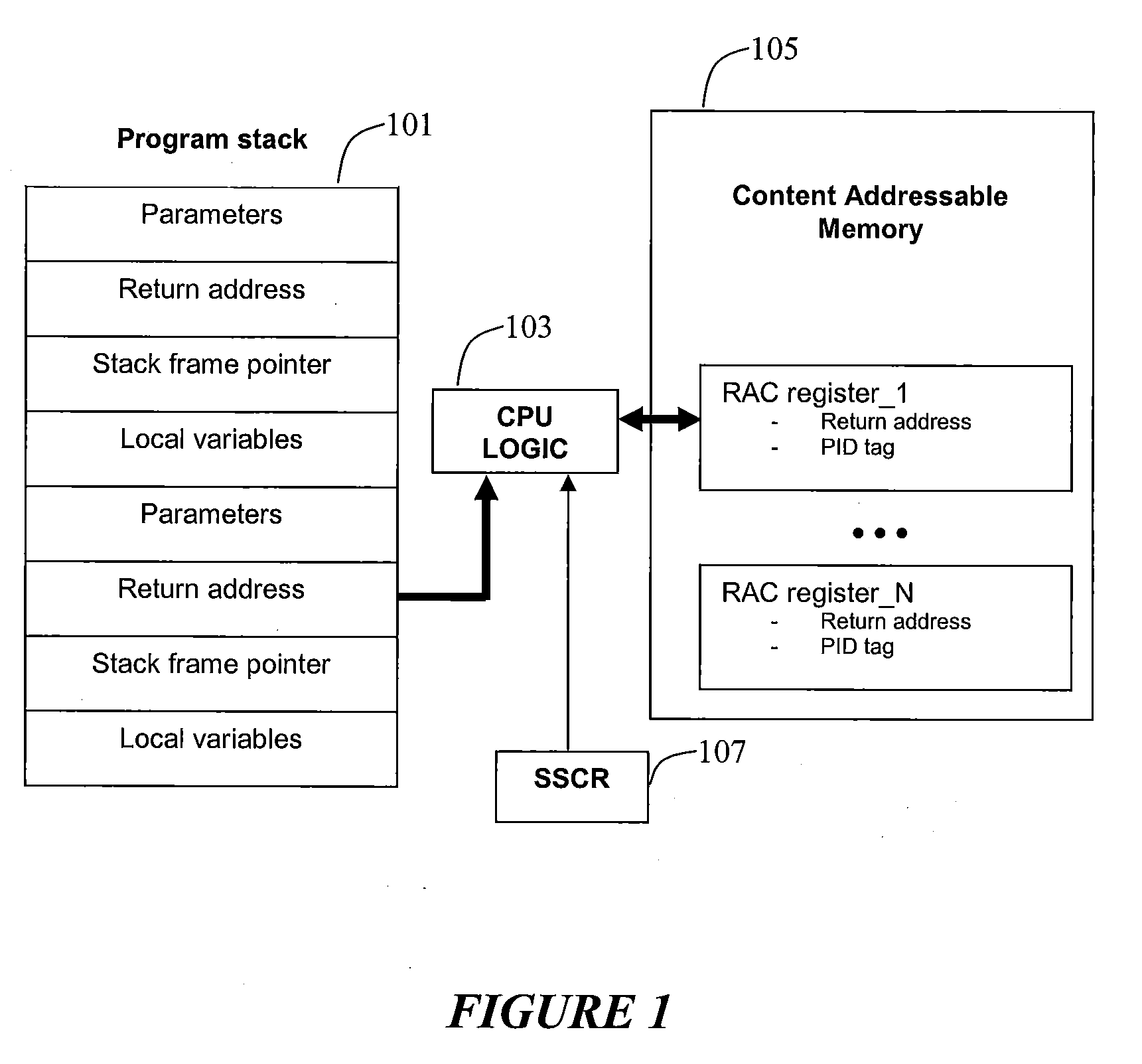
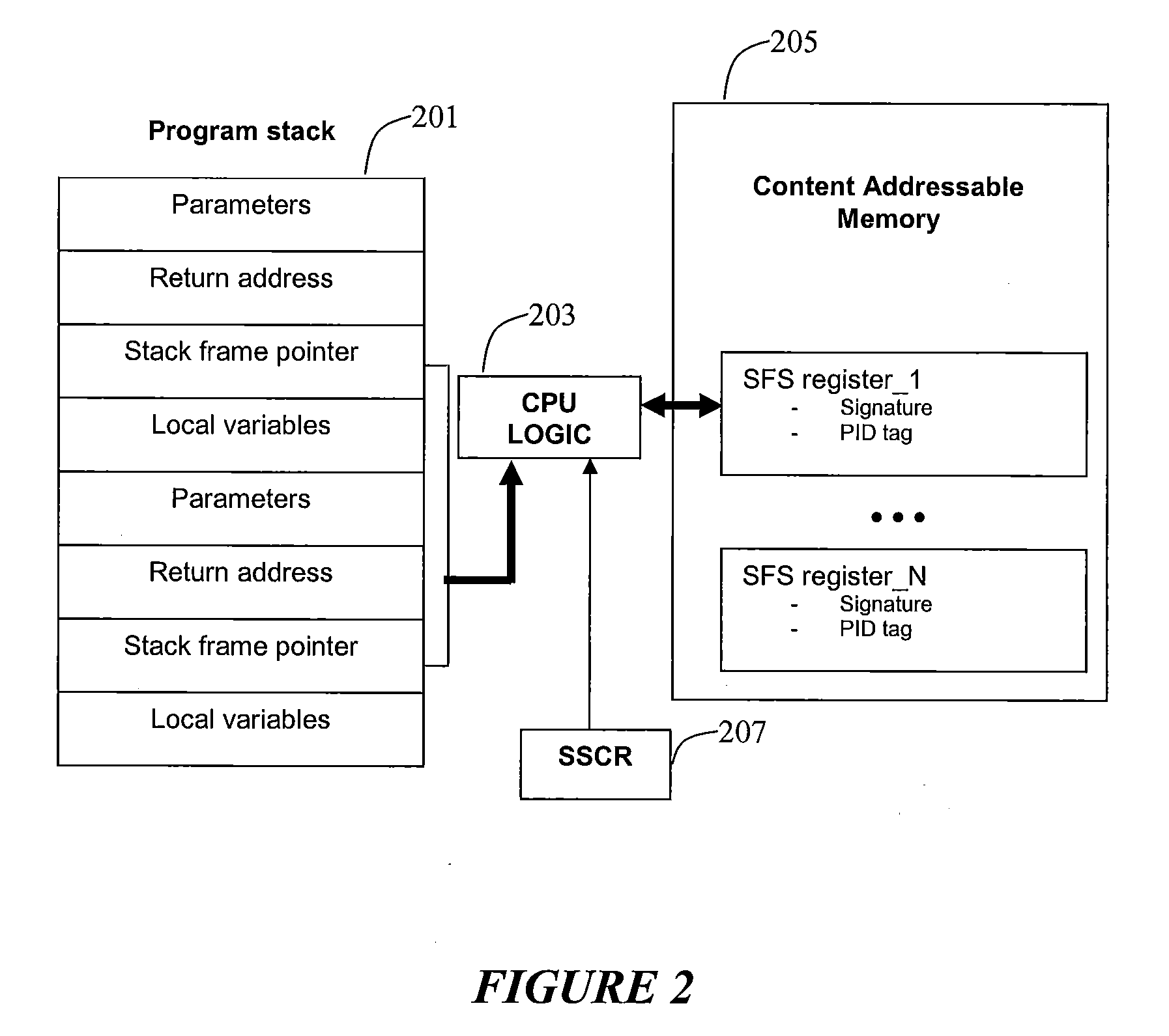
[0011]Aspects of the present invention relate to employing one or more of machine instructions (i.e. assembler language instructions) in a Central Processing Unit (CPU) to detect stack alterations. Aspects of the present invention also relate to employing one or more associated CPU registers to detect stack alterations. Aspects of the present invention also relate to employing CPU logic to detect stack alterations. Aspects of the present invention may also relate to employing hidden content addressable memory (CAM) and registers that are only accessible by the CPU, and each cell in the CAM may be accessed using a PID (processed, threaded) unique to the running program, such as the process ID or thread ID assigned by the operating system scheduler. The detection of stack alterations may enable the defeat of code injection via stack alteration attacks and otherwise corrupted stack frame memory leading to unpredictable or arbitrary program execution behavior.

[0012]The aspects of the pr...


PUM


Abstract

The disclosed systems and methods relate to employing one or more of machine instructions (i.e. assembler language instructions) to detect stack alterations. Aspects of the present invention also relate to employing CPU logic and one or more associated CPU registers to detect stack alterations. Aspects of the present invention may also relate to employing hidden content addressable memory (CAM) and registers that are only accessible by the CPU, and each cell in the CAM may be accessed using a PID unique to the running program, such as the process ID or thread ID assigned by the operating system scheduler.

Description

RELATED APPLICATIONS[0001][Not Applicable]FEDERALLY SPONSORED RESEARCH OR DEVELOPMENT[0002][Not Applicable]MICROFICHE / COPYRIGHT REFERENCE[0003][Not Applicable]BACKGROUND OF THE INVENTION[0004]Commercial software products may be vulnerable to code injection attacks against stack variables. For example, if a return address is changed, it may cause buffer overflows, format string errors, and integer overflows. This type of software corruption may lead to injection and execution of arbitrary code by an attacker.[0005]Further limitations and disadvantages of conventional and traditional approaches will become apparent to one of skill in the art, through comparison of such systems with some aspects of the present invention as set forth in the remainder of the present application with reference to the drawings.BRIEF SUMMARY OF THE INVENTION[0006]A system and / or method is provided for detecting stack alteration as shown in and / or described in connection with at least one of the figures, as ...

Claims


Application Information

Patent Timeline
23 Jul 2009
Publication
US20090187748A1
IPC
G06F9/30
CPC
G06F9/3004; G06F9/30134; G06F11/1004; G06F21/54; G06F9/3861
Inventors
KRIG, SCOTT