Hose Clamp

Inactive Publication Date: 2009-07-30
GM GLOBAL TECH OPERATIONS LLC
View PDF6 Cites 9 Cited by
  • Summary
  • Abstract
  • Description
  • Claims
  • Application Information

AI Technical Summary

Benefits of technology

[0009]An advantage of an embodiment is reduction of the space occupied by a hose clamp before and after its installation and use. The clamp has lower weight and cost and requires a shorter installation or removal time than a conventional hose clamp.

Problems solved by technology

For this reason, packaging of the components around hose attachments is difficult because of the extra space required for the clamp and for space reserved for handling during assembly and service operations.
Such components can be adversely affected by extremely aggressive clamping activity and because the clamps are made of spring steel.
Directly related to the complexity of conventional spring-loaded hose clamp designs, the weight and cost of the clamps are high, and the cost of tools for installing and removing them is high.

Method used


Image

  • Hose Clamp
  • Hose Clamp
  • Hose Clamp

Examples


Embodiment Construction

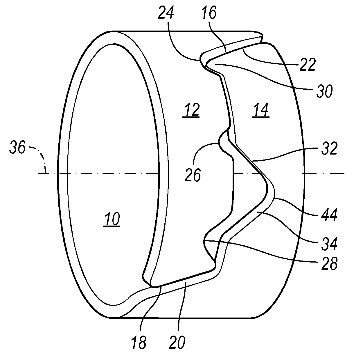
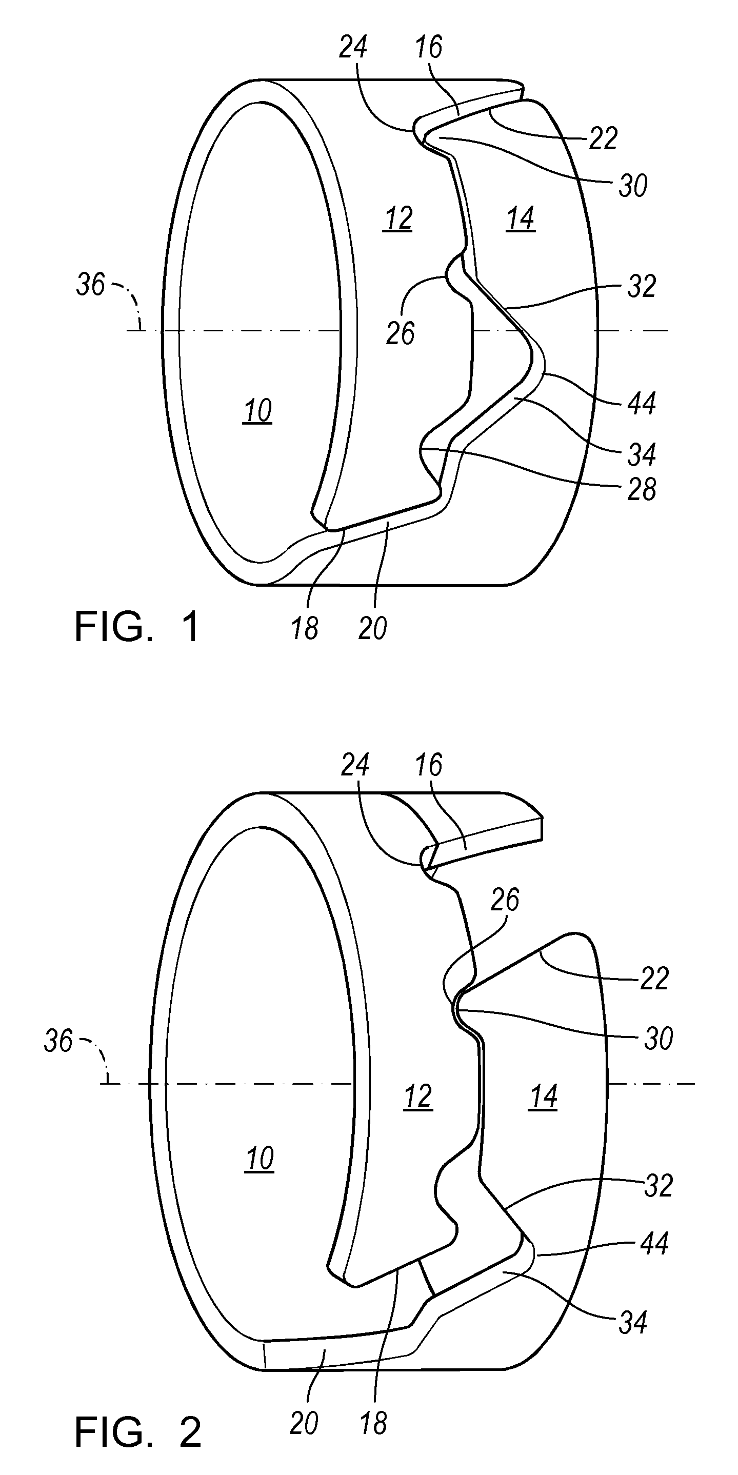
[0022]Referring first to FIG. 1, a first hose clamp 10 is formed in a circular, open-ended hoop of uniform thickness from elastically resilient material, preferably steel. FIG. 1 illustrates clamp 10 in its closed state. FIG. 2 illustrates clamp 10 in its open state, in which the clamp develops and maintains an elastic, resilient preload tending to restore the clamp to the closed state.

[0023]Clamp 10 includes first and second mutually parallel bands 12, 14 that extend along the circumference of the clamp, each band extending axially across a portion of the width of the clamp 10. A first transition surface 16 leads to band 12 and to its open end 18. A second transition surface 20 leads to band 14 and to its open end 22, which faces and is spaced from surface 16. Similarly, end 18 faces and is spaced from transition surface 20.

[0024]Band 12 is formed with recesses 24, 26, 28, which are spaced mutually along the circumference. Band 14 is formed with a projection 30, which can engage ea...


PUM


Abstract

A hose clamp for securing a hose to a component includes a first band of uniform thickness that extends angularly about an axis and includes an engagement surface, and a second band having the uniform thickness and formed in one piece with the first band, extending angularly about the axis, offset axially from the first band, and including a latch surface engageable with the engagement surface, the clamp having an open state in which the first band and the second band are elastically urged angularly about the axis toward contact with the hose, said engagement maintaining an elastically resilient load between the first band and the second band.

Description

BACKGROUND OF INVENTION[0001]The present invention relates generally to hose clamps, and more particularly to clamps used to interconnect and seal components of heating, ventilation and air conditioning (HVAC) systems connected by hoses.[0002]Conventional hose clamps used currently in HVAC systems in the automotive industry require access space around the clamps due to features of the clamp required to close and open the clamp. For this reason, packaging of the components around hose attachments is difficult because of the extra space required for the clamp and for space reserved for handling during assembly and service operations.[0003]Additional space around the clamps is required to provide adequate clearance from components that can be damaged due to contact with the clamp, such as wiring harnesses, hoses, plastic parts, etc. Such components can be adversely affected by extremely aggressive clamping activity and because the clamps are made of spring steel.[0004]Directly related ...

Claims


Application Information

Patent Timeline
IPC IPC(8): B65D63/04
CPCF16L33/03Y10T24/1484F24F13/0209
Inventor SERBU, LIVIURAJAIE, RICK H.
Owner GM GLOBAL TECH OPERATIONS LLC
Why Eureka
Try Eureka