Valve device

a valve and sealing member technology, applied in the direction of valve details, valve arrangement, operating means/releasing devices, etc., can solve the problems of generating particles, difficult to accurately control, and deterioration of sealing members, and achieve simple structure, easy control of radially outward movement amount, and constant pressing effect of sealing members

Inactive Publication Date: 2009-07-30
NIPPON VALQUA IND LTD
View PDF12 Cites 6 Cited by
  • Summary
  • Abstract
  • Description
  • Claims
  • Application Information

AI Technical Summary

Benefits of technology

[0021]As described above, a radially outward movement amount of the valve element unit depends on the eccentricity amount of the eccentric shaft portion of the eccentric shaft part. Therefore, it is possible to easily control the radially outward movement amount of the valve element unit to a fixed amount, only by setting the eccentricity amount of the eccentric shaft portion of the eccentric shaft part to a predetermined value. Therefore, with a simple structure, a constant pressing amount of the sealing members to the openings is achieved, and further an impact force of the sealing members to the openings can be reduced. As a result, it is possible to retard the deterioration of product life of the sealing members and further to prevent the generation of particles ascribable to the sealing members. Further, the rotation of the support is stopped by the stopper when the valve element unit is at the positions facing the openings. Accordingly, it is possible to prevent the valve element unit from shifting from the openings, thereby securely closing and airtightly sealing the openings.
[0022]In the third aspect of the invention, the rotation of the support is controlled by the magnitude relation between the rotational force applied to the support from the rotational force applier and the driving force from the driving source. Concretely, when the rotational force applied to the support from the rotational force applier and the driving force from the driving source compete with each other (when the forces act in opposite directions), the support and the valve element unit rotate in a direction in which a larger one of the rotational force and the driving force acts. Further, when the rotational force applied to the support from the rotational force applier and the driving force from the driving source act in the same direction, the support and the valve element unit rotate in the direction in which the rotational force and the driving force act. Therefore, by adjusting one of the rotational force from the rotational force applier and the driving force from the driving source, it is possible to easily control the rotation of the support.
[0023]In the fourth aspect of the invention, since the spiral spring is used as the rotational force applier, it is possible to apply the rotational force in one direction to the support from the spiral spring. Accordingly, it is possible to rotary drive the support and the eccentric shaft part in linkage with each other and to rotate the eccentric shaft part independently of the support by the driving source. As a result, it is possible to drive different driving mechanisms, that is, a rotating mechanism and a lifting mechanism by one driving mechanism. Further, since the spiral spring is used, it is possible to easily form the rotational force applier by using an existing component. This realizes a simple structure and a reduced manufacturing cost of the valve device.

Problems solved by technology

As a result, the sealing member tends to be deteriorated and broken, thereby generating a particle.
When the squeeze amount of the first sealing member and the second sealing member is set or controlled only through the thrust of the valve element driving unit, it is difficult to accurately control, thereby excessively crushing the first sealing member and the second sealing member.
As a result, it is difficult to achieve stable sealing performance, obtain a long product life of the first sealing member and the second sealing member, and prevent a particle.

Method used


Image

  • Valve device
  • Valve device
  • Valve device

Examples


first embodiment

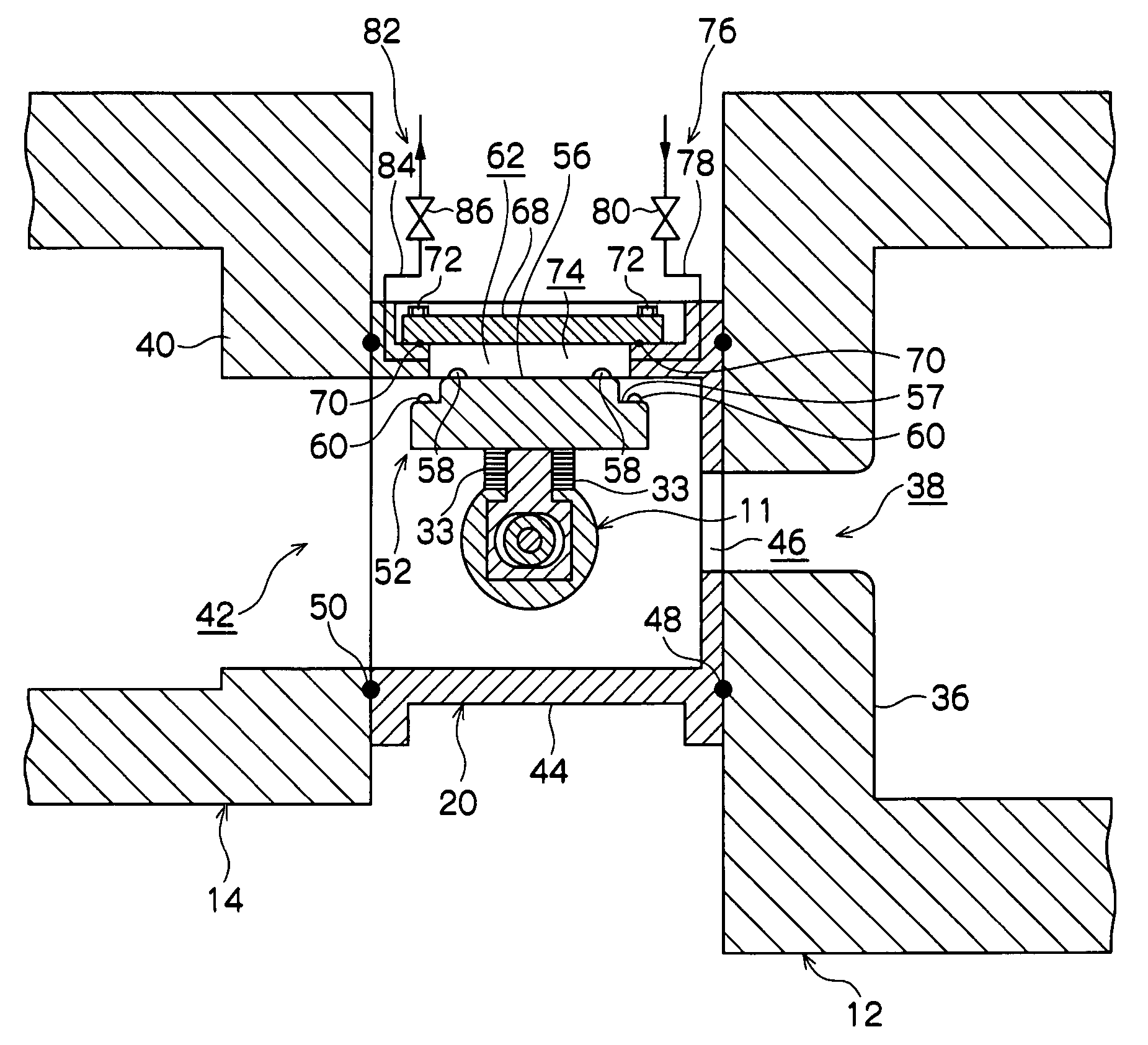
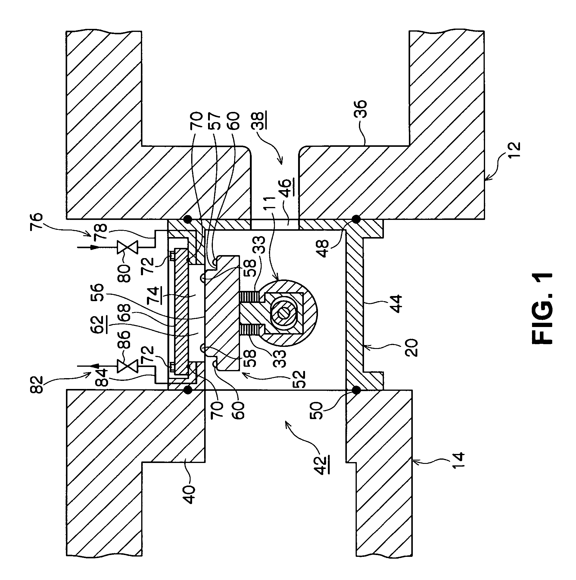
[0036]A gate valve device according to the present invention will be described with reference to the drawings. The following embodiments describe a form where the present invention is applied to the gate valve device as an example of a valve device.

[0037]As shown in FIG. 1, in a sidewall 36 defining a process chamber 12, a slender transfer port 38 through which a semiconductor wafer is passed to be loaded / unloaded is formed, and an opening 42 is formed also in a sidewall 40 defining a transfer chamber 14 communicatable with the process chamber 12. The gate valve device 20 has a casing 44 in a substantially rectangular parallelepiped shape made of, for example, aluminum. In one side of the casing 44, a slender first opening 46 communicating with the inside of the process chamber 12 is formed. On joint surfaces of the casing 44 joined to the process chamber 12 and the transfer chamber 14, O-rings 48, 50 are interposed respectively, so that airtightness can be maintained.

[0038]In the c...

second embodiment

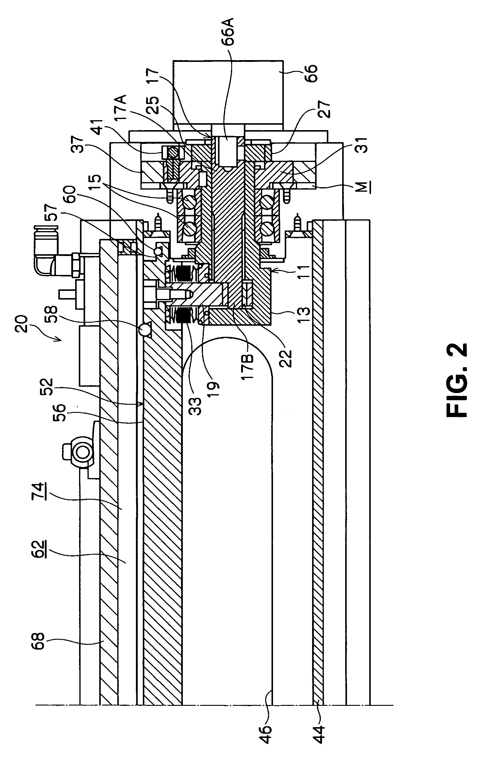
[0065]On the axial-direction-side plane 31A of the flange 31 of the gate valve device of the second embodiment, a cylindrical flange (stopper) 51 is attached instead of the pins. The cylindrical flange 51 is composed of a semicircular flange main body 53 and two first hook 61 and second hook 63 integrally formed with the flange main body 53. The semicircular flange main body 53 has a curved outer peripheral portion 65 greatly projecting outward and a groove-shaped inner peripheral portion 67 smaller in diameter than the outer peripheral portion 65. A groove 69 in which a shaft portion 79 of a later-described maintenance handle 77 enters for engagement is formed in the outer peripheral portion 65. Further, the inner peripheral portion 67 is formed so that a radially inner side thereof can accommodate a part of a ring-shaped member 25.

[0066]Further, the first hook 61 and the second hook 63 are integrally formed to extend from the outer peripheral portion 65 of the flange main body 53....


PUM


Abstract

A valve device includes a valve element unit for closing or opening a first opening formed in a casing; a valve element driving unit for rotating the valve element unit around an axis to move to a position facing the first opening, and for moving the valve element unit in a radial direction to seat at the first opening; a first sealing member provided on the valve element unit; and a stopper for restricting a rotation of the valve element unit. The valve element driving unit includes a support for supporting the valve element unit to be rotatable; a shaft part having an eccentric shaft portion connected to the valve element unit and having a center located at a position apart from a rotational center by a predetermined distance; and a driving source for rotating the shaft part. The stopper restricts a rotation of the support in one direction at a position where the valve element unit faces the opening.

Description

CROSS-REFERENCE TO RELATED APPLICATION[0001]This is a continuation application of the prior PCT application PCT / JP2007 / 065349, filed on Aug. 6, 2007, which is claiming the priority of Japanese Patent Application No. 2006-220507, filed on Aug. 11, 2006.TECHNICAL FIELD[0002]The present invention relates to a valve device used for a process chamber where a predetermined process is applied to an object to be processed such as a semiconductor wafer.BACKGROUND ART[0003]Generally, in a manufacturing process of a semiconductor device, various processes such as dry etching, sputtering, and CVD (Chemical Vapor Deposition) are repeatedly applied to a semiconductor wafer. Many of the various processes are performed under a vacuum atmosphere, and a load opening through which the wafer is loaded and unloaded into and from a process chamber for the processes is sealed with a gate valve device in a highly airtight state during the processes.[0004]A gate valve device of this type is mounted, for exa...

Claims


Application Information

Patent Timeline
Patent Type & Authority Applications(United States)
IPC IPC(8): F16K31/44
CPCF16K51/02F16K1/24F16K1/18
Inventor NISHIBA, TAKEHIRO
Owner NIPPON VALQUA IND LTD
Why Eureka
Try Eureka