Document feeder

a feeder and document technology, applied in the direction of thin material handling, article separation, electrical equipment, etc., can solve the problem of complex structure of the ad

Active Publication Date: 2009-07-30
BROTHER KOGYO KK
View PDF21 Cites 19 Cited by
  • Summary
  • Abstract
  • Description
  • Claims
  • Application Information

AI Technical Summary

Benefits of technology

[0010]The present invention provides a thin document feeder with a simple and compact structure, wherein a substantially U-shaped document transporting pathway is provided and a document discharging portion is provided at a position that is higher than a position where a document feeding portion is provided.
[0012]With this structure, the positions where the pulling device and the separating-transporting device are provided are lower than the highest point of the reverse transporting mechanism. Accordingly, the document feeder can be prevented from becoming large in height.
[0014]With this structure, the positions where the pulling roller and the separating roller are provided are lower than the highest point of the reverse roller. Accordingly, the sheet feeder can be prevented from becoming large in height.

Problems solved by technology

The structure of the ADF becomes complicated when driving systems of the above members are also taken into consideration.

Method used


Image

  • Document feeder
  • Document feeder
  • Document feeder

Examples


first embodiment

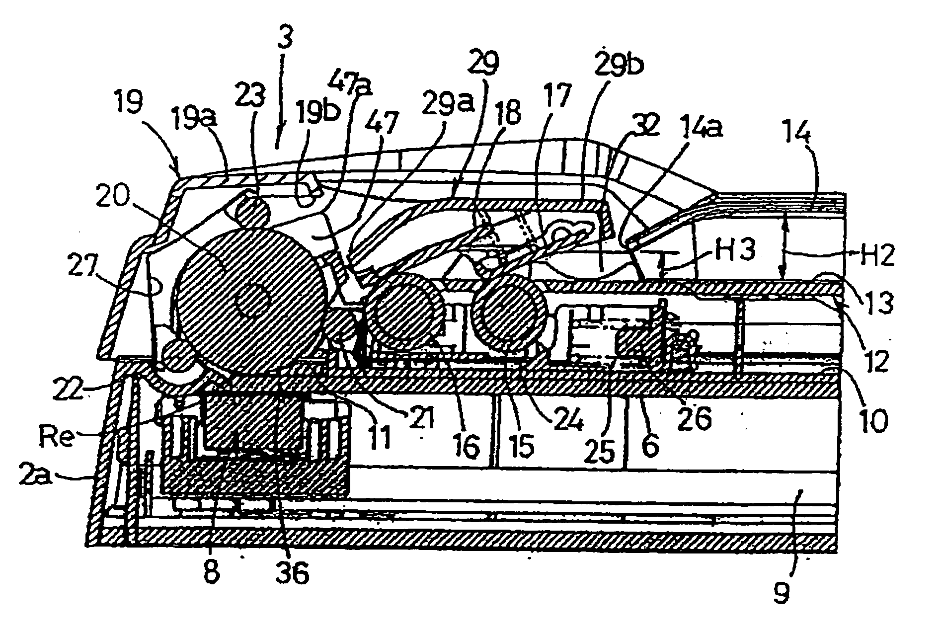
[0038]In the first embodiment, as shown in FIGS. 5-7 and 9, two rotation driving rollers (a pulling roller 15 and a separating roller 16, which are provided in this order from the upstream side with respect to the document conveying direction) functioning as the first rotation driving member and a reverse roller 20 with a large diameter functioning as the second rotation driving member are arranged substantially at a central portion of a direction perpendicular to the document conveying direction (i.e. the direction along the width of the document D), above the pressing plate 10 (referring to FIG. 12). The reading position Re linearly extends in a direction perpendicular to the document conveying direction. A rotation axis of a driving shaft 28 that supports the reverse roller 20 coincides with the reading position Re in the plan view. Thus, the lower surface of the peripheral surface of the reverse roller 20 faces the reading surface of the reading device 8 when the reading device ...

second embodiment

[0052]A second embodiment for ensuring the above effect is shown in FIGS. 3, 4, 6, 7 and 13. A pair of engaging members 46 having a substantially semicylindrical shape in cross-section is disposed on the sides of the reverse roller 20 while sandwiching the reverse roller 20 therebetween, so as to extend in the width direction of the document D. Each of the engaging members 46 is disposed above each of the respective first pressing members 40 and continues to the upper part of each of the respective first pressing members 40. The pair of engaging members 46 covers the driving shaft 28 from the upper side. Each of the respective engaging members 46 is connected with each of the respective first pressing members 40 by an engaging device (not shown). A plurality of rib-shaped guiding members 47 is integrally formed on outer surfaces of the engaging members 46, at predetermined intervals, along the extension direction of the driving shaft 28. The guiding members 47 extend diagonally upwa...

fourth embodiment

[0056]A fourth embodiment for maintaining the stacking order of the discharged documents D in the normal order is shown in FIG. 13. A plurality of sweeping rollers 51 is disposed at a substantially same height as the third pinch roller 23 located at the most downstream position in the document conveying direction. The sweeping rollers 51 can be a cylindrical roller with protrusions individually arranged on the periphery thereof at predetermined intervals, can be a roller having a spur-like cross section, or can be a spur made of a thin plate. The plurality of sweeping rollers 51 is arranged facing the outer surfaces of the engaging members 46 or the reverse roller 20. When the sweeping rollers 51 are disposed facing the outer surfaces of the engaging members 46, the sweeping rollers 51 are preferably willingly rotated. According to the structure of this embodiment, because of the rotation of the sweeping rollers 51, the front end of the document D that is released from the contact p...


PUM


Abstract

A document feeder includes a reverse transporting mechanism that forms a substantially U-shaped document transporting pathway for carrying a document from a feeding tray located at a lower side to a discharging tray located at an upper side through a reading position, a pulling device, a separating-transporting device and a openable pathway cover. The pulling device and the separating-transporting device are arranged at substantially the same horizontal level within the height that is occupied by the reverse transporting mechanism. The pathway cover is capable of opening and closing to cover on the pulling device, the separating-transporting device and the reverse transporting mechanism.

Description

CROSS-REFERENCE TO RELATED APPLICATION[0001]This is a Divisional Application of application Ser. No. 11 / 073,873 filed Mar. 8, 2005, which claims priority from Japanese Patent Application No. 2004-064657, filed on Mar. 8, 2004, the subject matter of which are incorporated herein in their entirety by reference thereto.BACKGROUND OF THE INVENTION[0002]1. Field of the Invention[0003]The present invention relates to a document feeder provided to an image reader having a reading device that reads an image, at a reading position, from a document that is being conveyed. The present invention particularly relates to a thin document feeder having a substantially U-shaped document transporting pathway for conveying the document from a sheet feeding portion to a sheet discharging portion through the reading position.[0004]2. Description of the Related Art[0005]There is an imaging reader that is capable of reading an image recording surface of a stationary document and a moving document. Such th...

Claims


Application Information

Patent Timeline
Patent Type & Authority Applications(United States)
IPC IPC(8): B65H5/06B65H3/46B65H3/52B65H3/68H04N1/00H04N1/04
CPCH04N1/04B65H5/26B65H7/00H04N1/00602B65H15/00B65H5/062B65H29/125
Inventor OHAMA, TAKASHIOSAKABE, YOSHINORIIWAGO, TOSHITAKA
Owner BROTHER KOGYO KK
Why Eureka
Try Eureka