Electric motor stator winding temperature estimation

a stator winding and electric motor technology, applied in the direction of electric generator control, dynamo-electric converter control, dynamo-electric gear control, etc., can solve the problems of unbalanced current flow, no current flow, permanent magnet motor damage in electric motor system, etc., to prevent overheating damage

Active Publication Date: 2009-07-30
GM GLOBAL TECH OPERATIONS LLC
View PDF9 Cites 79 Cited by
  • Summary
  • Abstract
  • Description
  • Claims
  • Application Information

AI Technical Summary

Benefits of technology

[0004]A temperature estimation controller is provided for preventing overheating damage to stator windings of a permanent magnet motor. The temperature estimation controller includes a low speed temperature estimation module, a transition module and a temperature dependent torque command derater block. The low speed temperature estimation module determines a stator temperature of each of a plurality of phases of the permanent magnet motor in response to first thermal impedances measured for each of the plurality of phases with respect to a thermal neutral. The transition module is coupled to the low speed temperature estimation module and outputs the stator temperature of each of a plurality of phases of the permanent magnet motor as determined by the low speed temperature estimation module when a detected speed of the permanent magnet motor is less than a first predetermined speed. The temperature dependent torque command derater block is coupled to the transition module and derates the torque command in response to the stator temperature of one or more of the plurality of phases.

Problems solved by technology

A permanent magnet motor in an electric motor system can be damaged when the temperature of stator windings of the permanent magnet motor become overheated.
At or near zero speed, however, no current may be flowing in the phase of the electric motor stator winding where the sensor is installed or, at certain speeds, unbalanced currents may be flowing in the three phases of the stator windings.
Under these conditions, the single temperature measurement sensor will not correctly report the actual temperature of the electric motor and, consequently, the electric motor can be damaged by overheating.

Method used


Image

  • Electric motor stator winding temperature estimation
  • Electric motor stator winding temperature estimation
  • Electric motor stator winding temperature estimation

Examples


Embodiment Construction

[0014]The following detailed description is merely exemplary in nature and is not intended to limit the invention or the application and uses of the invention. Furthermore, there is no intention to be bound by any expressed or implied theory presented in the preceding technical field, background, brief summary or the following detailed description.

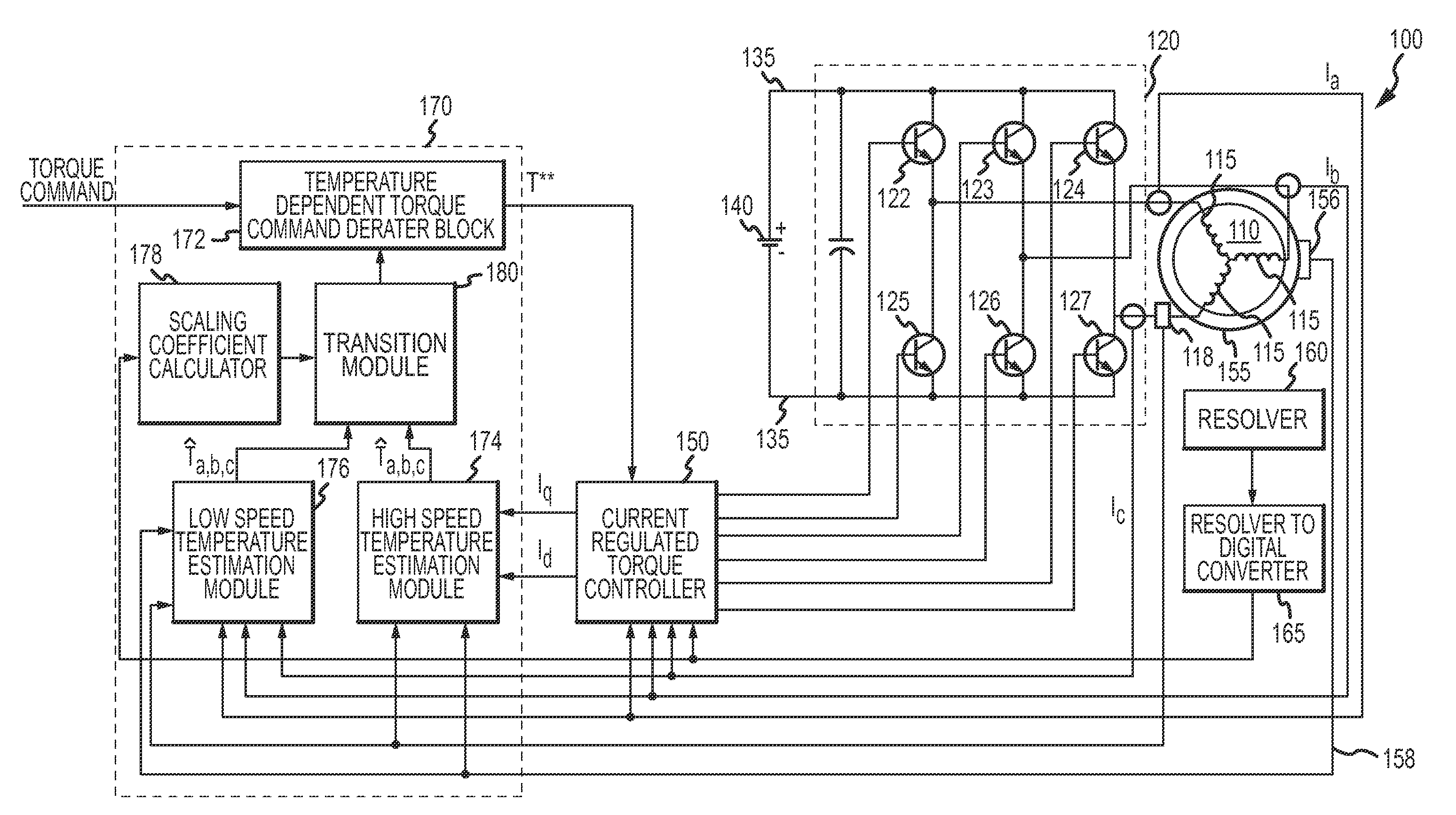
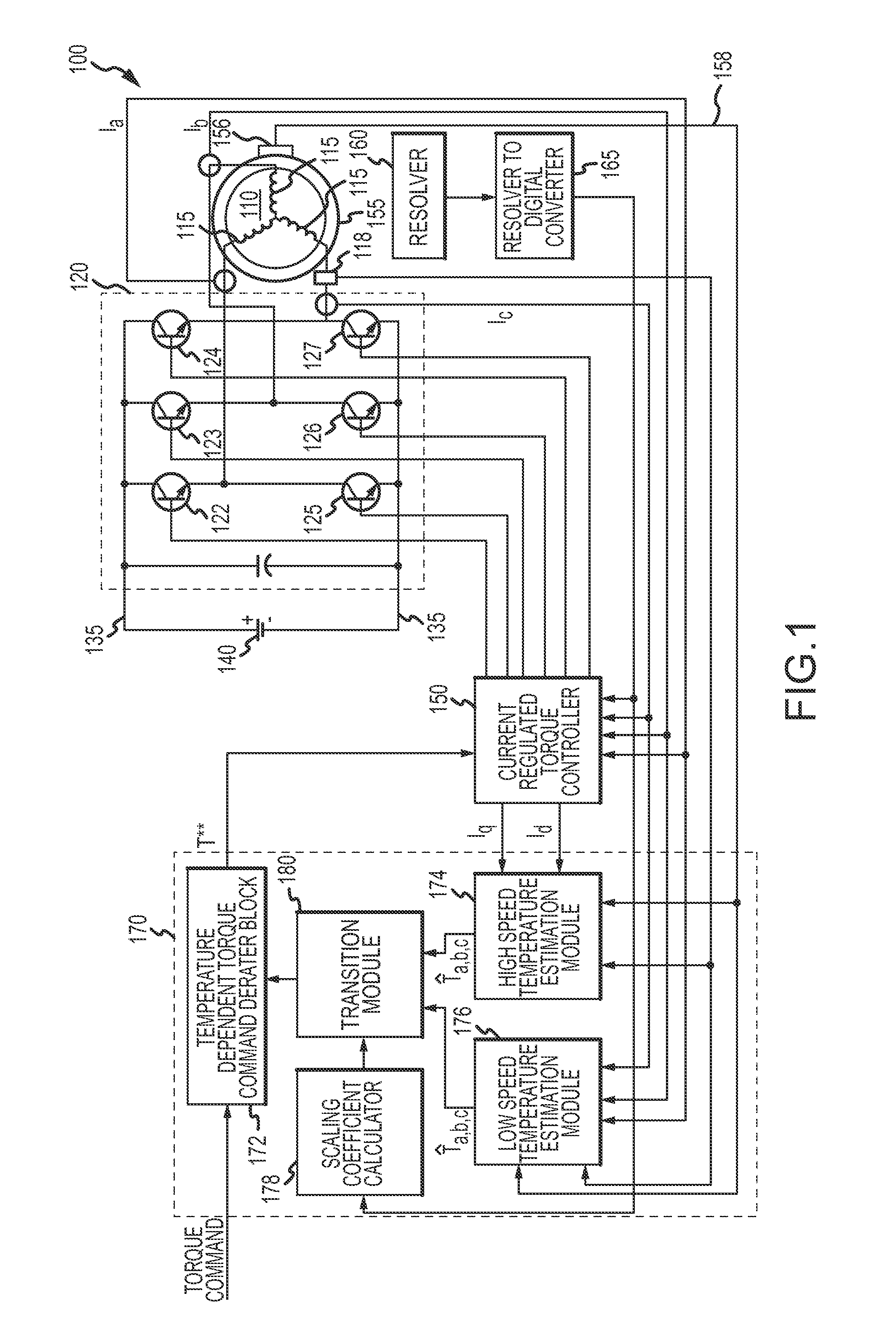
[0015]Referring to FIG. 1, an electric motor system 100 in accordance with an embodiment of the present invention includes a three-phase alternating current (AC) synchronous electric machine 110, such as a synchronous reluctance machine or a permanent magnet electric motor, which operates in response to signals from an inverter 120. The inverter 120 providing electric control for the electric motor 110 is connected between direct current (DC) bus lines 135 of a power source 140. The inverter 120 includes transistors 122 to 127, such as Insulated Gate Bipolar Transistors (IGBTs), and operates in response to signals from a current regulated ...


PUM


Abstract

A temperature estimation controller and methods are provided for controlling a torque command to prevent overheating of one or more of a plurality of phases of a permanent magnet motor. The temperature estimation controller includes a low speed temperature estimation module, a transition module and a temperature dependent torque command derater block. The low speed temperature estimation module determines a stator temperature of each of a plurality of phases of the permanent magnet motor in response to first thermal impedances measured for each of the plurality of phases with respect to a thermal neutral. The transition module is coupled to the low speed temperature estimation module and outputs the stator temperature of each of a plurality of phases of the permanent magnet motor as determined by the low speed temperature estimation module when a detected speed of the permanent magnet motor is less than a first predetermined speed. The temperature dependent torque command derater block is coupled to the transition module and derates the torque command in response to the stator temperature of one or more of the plurality of phases.

Description

TECHNICAL FIELD[0001]The present invention generally relates to electric motor systems, and more particularly relates to a method and an apparatus for estimating the temperature of stator windings in an electric motor.BACKGROUND OF THE INVENTION[0002]A permanent magnet motor in an electric motor system can be damaged when the temperature of stator windings of the permanent magnet motor become overheated. Typically, the temperature of the stator windings is measured by a temperature measurement sensor, such as a thermistor, installed on one of the phases of the electric motor stator winding. Assuming balanced three phase currents are flowing in the stator windings, the single temperature measurement sensor may adequately estimate the temperature of all three phases. At or near zero speed, however, no current may be flowing in the phase of the electric motor stator winding where the sensor is installed or, at certain speeds, unbalanced currents may be flowing in the three phases of th...

Claims


Application Information

Patent Timeline
Patent Type & Authority Applications(United States)
IPC IPC(8): H02P23/14H02K9/00H02K11/00
CPCH02H7/0852
Inventor PATEL, NITINKUMAR R.SON, YO CHANHITI, SILVASCHULZ, STEVEN E.
Owner GM GLOBAL TECH OPERATIONS LLC
Why Eureka
Try Eureka