Charge control circuit, charging device, and connection checking method

a control circuit and charging device technology, applied in the direction of secondary cells servicing/maintenance, safety/protection circuits, instruments, etc., can solve the problems of increasing the failure to directly detect the electrical connection, and so as to increase the overall size or cost of the charging device

Inactive Publication Date: 2009-07-30
RICOH ELECTRONIC DEVICES CO LTD
View PDF2 Cites 25 Cited by
  • Summary
  • Abstract
  • Description
  • Claims
  • Application Information

AI Technical Summary

Benefits of technology

[0007]Example embodiments of the present invention provide a charge control circuit, charging device, and / or a connection checking method, capable of checking electrical connection between a charging device and a secondary battery, without substantially increasing the overall size or cost of the charging device.
[0011]Additionally, the controller may further reduce the value of the charge current after the value of the battery voltage reaches the third reference voltage value during the charging operation, start a charge end wait time after the value of the charge current reaches below a reference current value, determine whether the value of the charge current during the charge end wait time is equal to or greater than a first current value based on the comparison result to generate a fourth determination result, and control the on or off state of the transistor after the charge end wait time according to the fourth determination result.
[0013]Other example embodiments of the present invention provide a charge control circuit, a charging device, and a connection checking method of checking electrical connection between a charging device and a secondary battery, without substantially increasing the work or time required for manufacturing or modifying the charging device.

Problems solved by technology

However, this approach fails to directly detect the electrical connection.
Further, providing the switch or the temperature sensitive element may increase the overall size or cost of the charging device.
Since defining the range requires at least two threshold values in addition to the threshold value for detecting the full charge, the overall size or cost of the charging device may increase.
Further, the Japanese Patent No. 3203538 fails to address the example case in which the secondary battery is in the over discharge state.
In order to perform intermittent charging in addition to constant current voltage charging, the additional circuit for intermittent charging is required such that the overall size or cost of the charging device may increase.

Method used


Image

  • Charge control circuit, charging device, and connection checking method
  • Charge control circuit, charging device, and connection checking method
  • Charge control circuit, charging device, and connection checking method

Examples


Embodiment Construction

[0021]In describing the example embodiments illustrated in the drawings, specific terminology is employed for clarity. However, the disclosure of this patent specification is not intended to be limited to the specific terminology selected and it is to be understood that each specific element includes all technical equivalents that operate in a similar manner. For example, the singular forms “a”, “an” and “the” are intended to include the plural forms as well, unless the context clearly indicates otherwise.

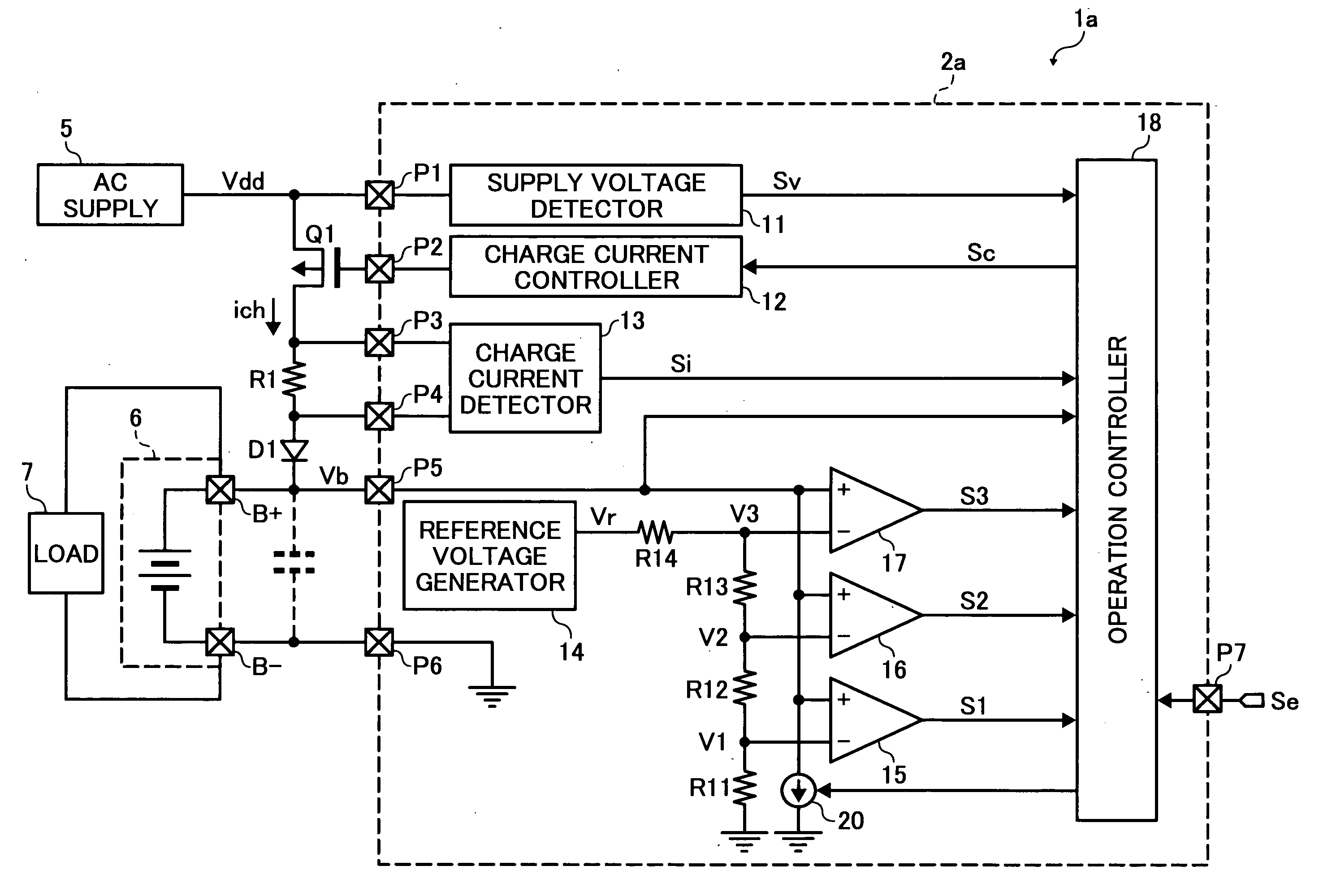
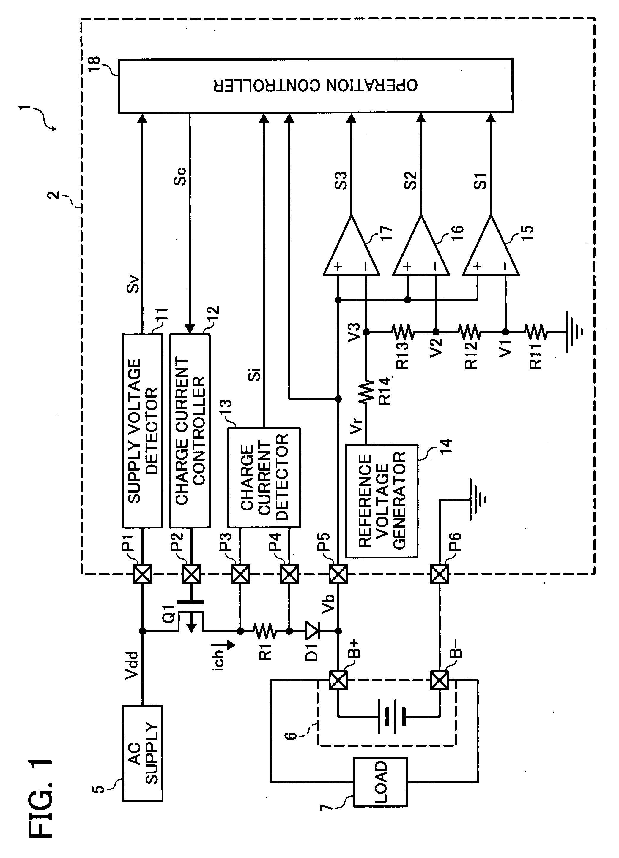
[0022]Referring now to the drawings, wherein like reference numerals designate identical or corresponding parts throughout the several views, FIG. 1 illustrates a charging device 1 according to an example embodiment of the present invention. Referring to FIG. 1, the charging device 1 is coupled to an alternate current power supply (“AC supply”) 5, which supplies electric power to the charging device 1, such as an AC adopter. The charging device 1 is further coupled to a secondary b...


PUM


Abstract

Electrical connection between a charging device and a secondary battery is checked during a wait time in which a charge mode of the charging device is selected. When the electrical connection is not successfully established, a charge current is not supplied from the charging device to the secondary battery.

Description

CROSS-REFERENCE TO RELATED APPLICATIONS[0001]This patent application is based on and claims priority under 35 U.S.C. §119 to Japanese patent application No. 2006-052700 filed on Feb. 28, 2006, in the Japanese Patent Office, the entire contents of which are hereby incorporated by reference.FIELD OF THE INVENTION[0002]Example embodiments of the present invention relate generally to a charge control circuit for controlling operation of a transistor supplying a charge current to a secondary battery, a charging device incorporating the charge control circuit, and a method of checking electrical connection between the charging device and the secondary battery.DESCRIPTION OF THE RELATED ART[0003]In order to charge a secondary battery using a charging device, electrical connection between the secondary battery and the charging device may need to be checked periodically during charging operation or before starting the charging operation.[0004]In one example, the electrical connection between...

Claims


Application Information

Patent Timeline
Patent Type & Authority Applications(United States)
IPC IPC(8): H02J7/10
CPCH01M10/44H02J7/0072H02J7/0036H01M10/48Y02E60/10H02J7/0071H02J7/00714H02J7/007182H02J7/00309H02J7/0029G01R19/16542
Inventor KAMATANI, TOMOHIKO
Owner RICOH ELECTRONIC DEVICES CO LTD
Why Eureka
Try Eureka